Method and apparatus to dynamically adjust resource power usage in a distributed system

a distributed system and resource technology, applied in the field of power management, can solve the problems of ineffective latency of turning on/off units, likely power management problems of architecture,

Inactive Publication Date: 2008-01-03
INTEL CORP
View PDF20 Cites 38 Cited by
  • Summary
  • Abstract
  • Description
  • Claims
  • Application Information

AI Technical Summary

Problems solved by technology

This architecture will likely experience difficulties in power management.
As a result, conventional activity detector circuitry cannot effectively hide the latency

Method used


Image

  • Method and apparatus to dynamically adjust resource power usage in a distributed system
  • Method and apparatus to dynamically adjust resource power usage in a distributed system
  • Method and apparatus to dynamically adjust resource power usage in a distributed system

Examples


Embodiment Construction

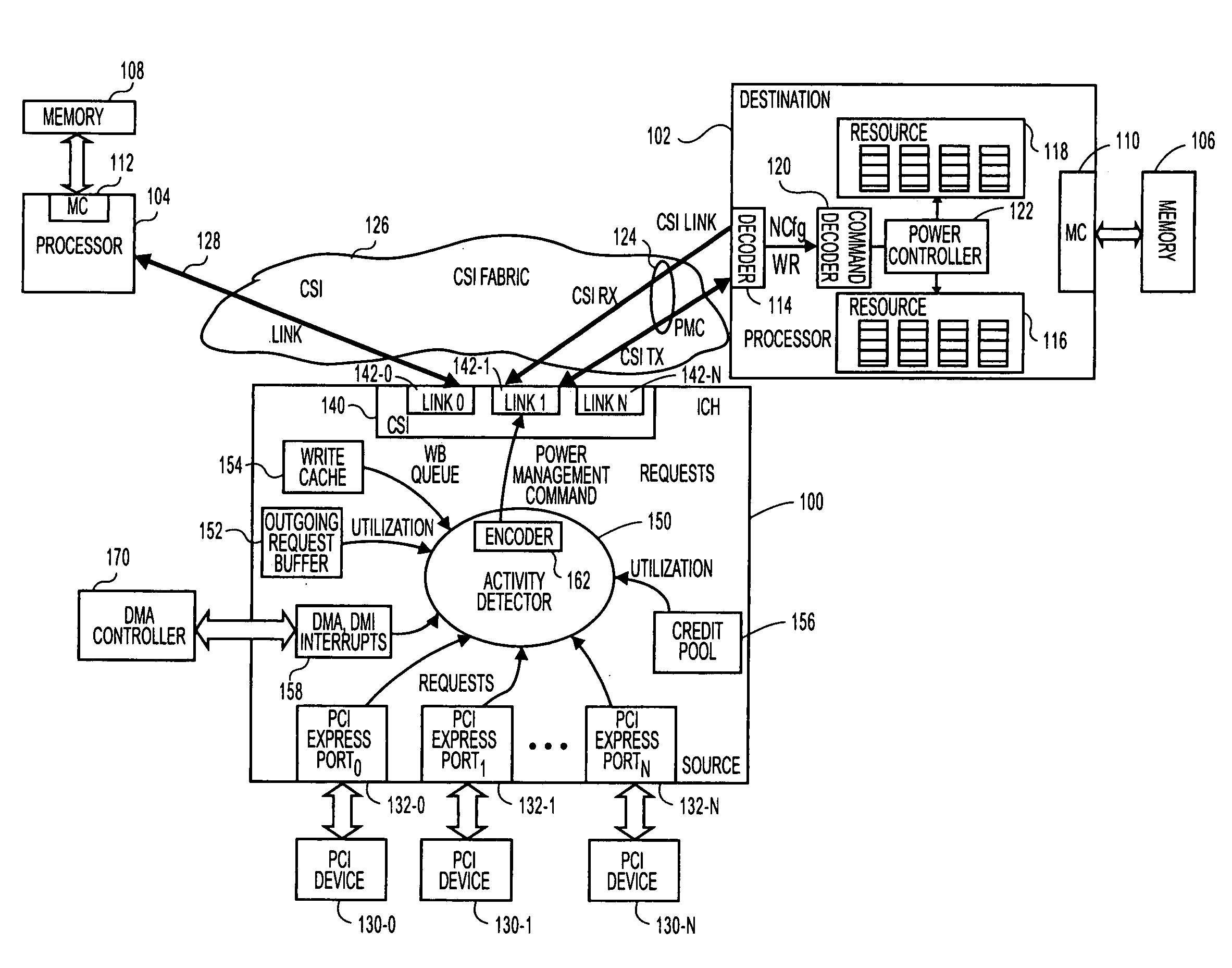
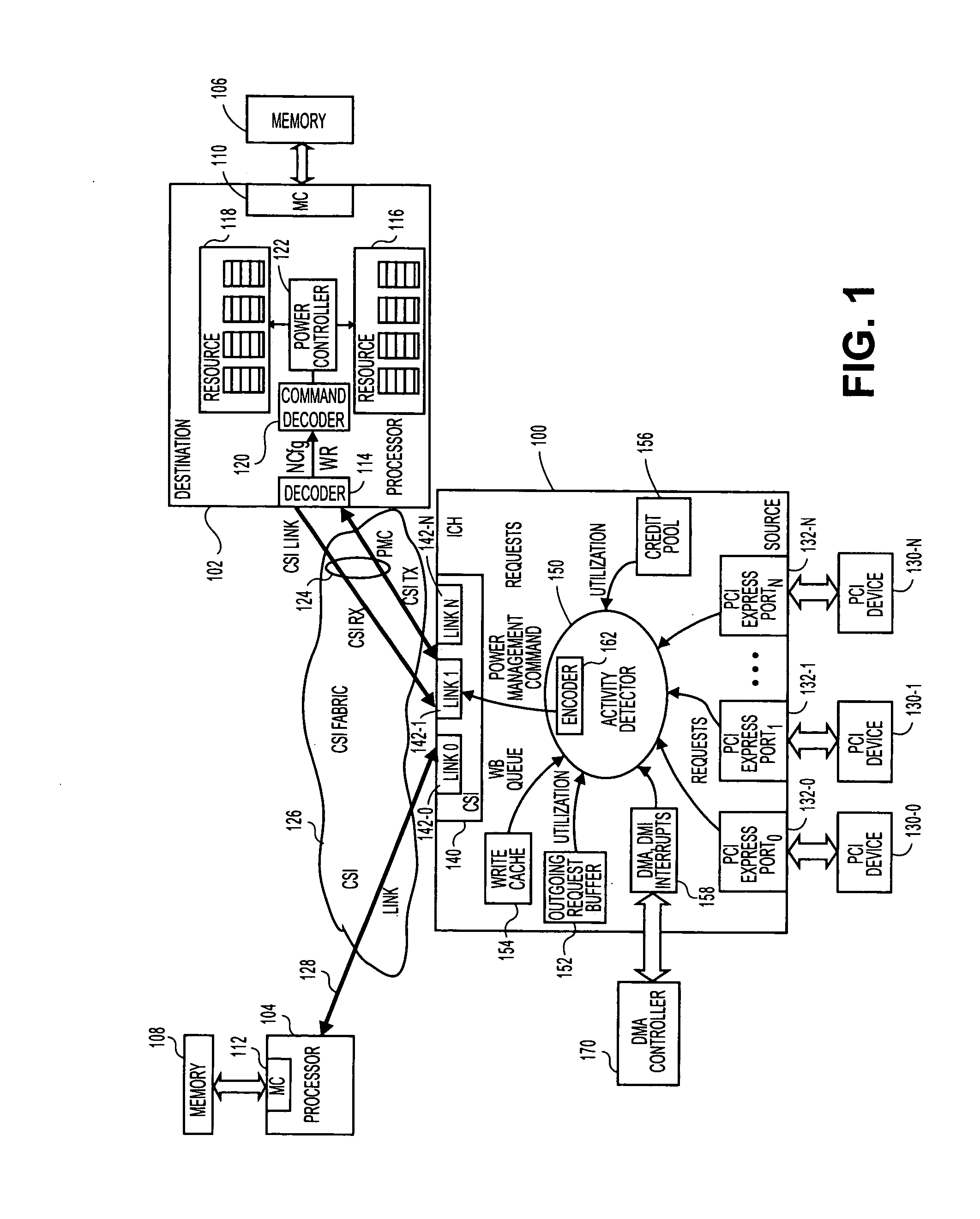
[0011]FIG. 1 is a block diagram of a dual processor system of one embodiment of the invention. Such a dual processor (DP) embodiment and may occur in a variety of possible platforms. For example, this embodiment may be implemented as a desk top or mobile computer, a server, a set top box, a personal digital assistant (PDA), an alphanumeric pager, cellular telephone, or any other type of wireless communication device.

[0012]In this embodiment, two destinations (processor 102 and processor 104) are communicatively coupled to a source. In this example, input / output hub (IOH) 100 by point-to-point links 124, 128. A “link” is generally defined as an information-carrying medium that establishes a communication pathway for messages, namely information placed in a predetermined format. The link may be a wired physical medium (e.g., a bus, one or more electrical wires, trace, cable, etc.) or a wireless medium (e.g., air in combination with wireless signaling technology).

[0013]In some embodime...


PUM


Abstract

A system and method to provide source controlled dynamic power management. An activity detector in a source determines expected future resource usage. Based on that expected usage, the source generates a power management command and sends that command to a destination. The destination then adjusts the power level of the resource based in the command.

Description

BACKGROUND OF THE INVENTION[0001]1. Field[0002]Embodiments of the invention relate to power management. More specifically, embodiments relate to source controlled dynamic power management.[0003]2. Background[0004]Microprocessors commonly use dynamic power management techniques to manage power usage. Normally, dynamic power management for microprocessors is accomplished through activity detector circuitry that is located in the microprocessor and coupled to a centralized, front side bus (FSB). The activity detector circuitry is adapted to detect conditions under which certain units should be turned on or off and to adjust the power levels of these units appropriately.[0005]Traditionally, the activity detector circuitry has provided acceptable performance because such circuitry was physically separated from the power-controlled units by only a short distance. However, bus architectures are moving away from FSB architectures and are beginning to utilize point-to-point architectures. On...

Claims


Application Information

Patent Timeline
IPC IPC(8): H04B7/185
CPCY02B60/1278G06F1/3203Y02B60/1282G06F1/3287Y02D10/00
Inventor HUTSELL, STEVEN R.SISTLA, KRISHNAKANTHLIU, YEN-CHENG
Owner INTEL CORP
Why Eureka
Try Eureka