
Modular mold system for production of product families

a technology of modular injection molds and product families, which is applied in the field of optimizing modular injection mold systems, can solve the problems of not being able to easily optimize for larger cavitation molds, not being able to meet the needs of specific new or unique items, and traditional dedicated custom mold systems are both expensive and time-consuming to develop

Inactive Publication Date: 2008-01-03
THE PROCTER & GAMBLE COMPANY
View PDF34 Cites 34 Cited by
  • Summary
  • Abstract
  • Description
  • Claims
  • Application Information

AI Technical Summary

Benefits of technology

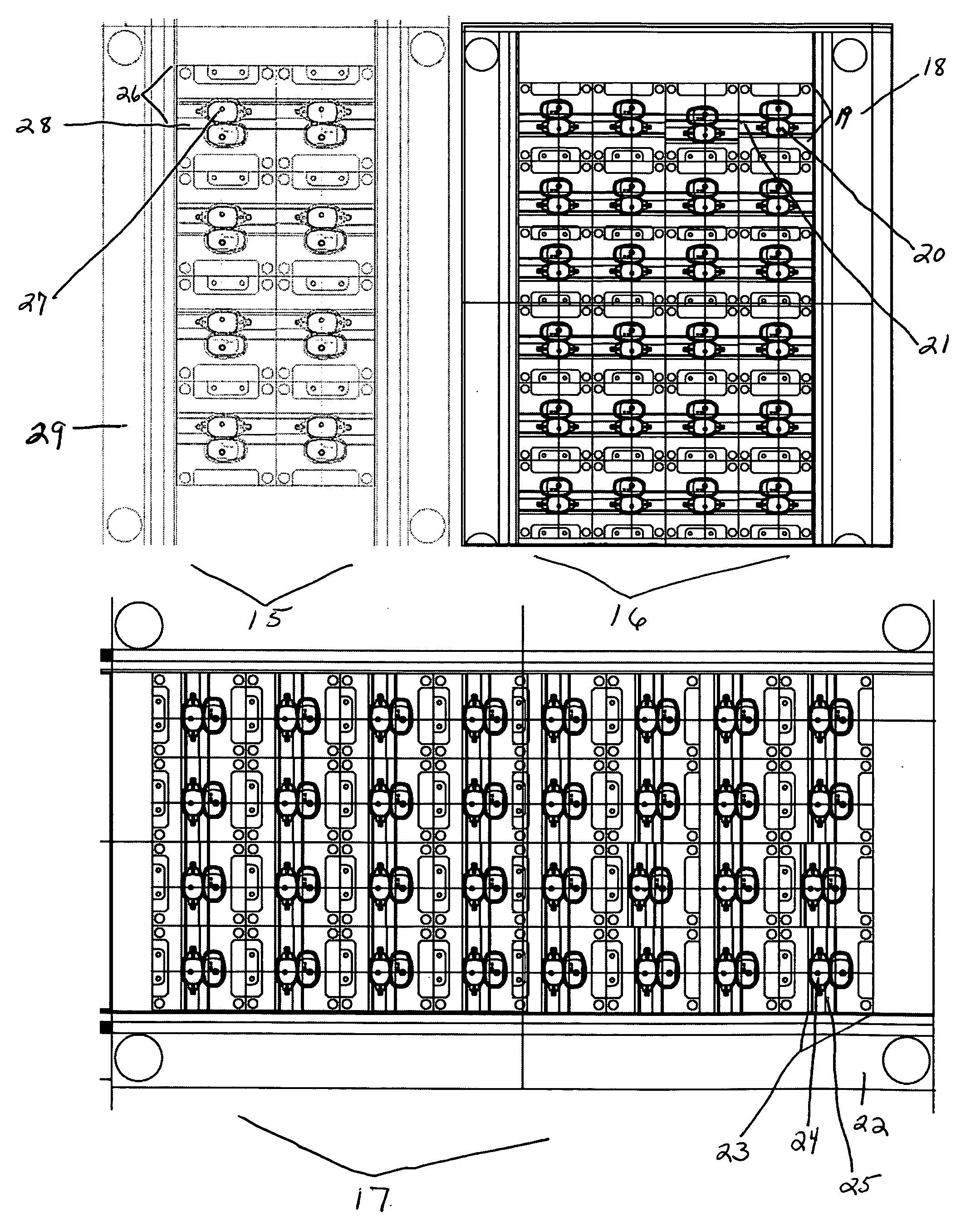
[0071] In another embodiment, the present invention is directed to a modular mold system comprising multiple mold designs / sizes and multiple mold insert designs / sizes all utilizing a specific / special coating to allow for production of high clarity / high gloss items or components.
[0078] The following examples further describe and demonstrate the preferred embodiments within the scope of the present invention. The examples are given solely for the purpose of illustration, and are not to be construed as limitations of the present invention since many variations thereof are possible without departing from its scope Table 1 below is an embodiment of the present invention, further illustrating some benefits of the present invention's modular mold system: TABLE 1OptimizedConventionalCurrentModular MoldAttributeMoldsModular MoldsSystemComponentsLow BenefitLow BenefitHigh Benefitwhich canbe used forother moldswithoutmodificatione.g: moldplatesMoldUniqueUnique for eachMost flexible - bothdesign(s)for eachdesign - moldmultiple moldpart size / inserts verydesigns anddesignsimilarmultiple moldinserts based onfamily of partdesigns.Size / designNAMust be IdenticalMold systemof moldor very similardesigned toinsertoptimize the insertbased on part designand family ofdesigns.SizeGenerally fixedFixed in designof moldstage of the part(s)to be producedShape andNAMust be identicalMust be similar -part designor very similar.but mold system isdesigned to allowmore variability insize to deliverfamily of design.Part sizeMust be similarDifferent - Moldsystem designed toallow for variabilityin size.SavingLowMed-HighVery high (if manypotentialBenefitpart sizes will beused in one modularmold system)
[0079] All documents cited in the Detailed Description of the Invention are, in relevant part, incorporated herein by reference; the citation of any document is not to be construed as an admission that it is prior art with respect to the present invention. To the extent that any meaning or definition of a term in this written document conflicts with any meaning or definition of the term in a document incorporated by reference, the meaning or definition assigned to the term in this written document shall govern.

Problems solved by technology

These systems have disadvantages in that they are not easily optimized for larger cavitations molds; they have very few common components that can be used in other modular molds without modification.
In other words, these modular molds are usually very specialized to produce a specific part design with specific dimensions and not interchangeable with other modular molds or they are so generically designed as to be not efficient in producing items of varying sizes on a large scale i.e. large cavitations molds.
This traditional dedicated custom mold system is both very expensive and very time consuming to develop.
However, these systems have inherit disadvantages such as the mold designs are not designed and built to be optimal with a specific item design, often insert designs and dimensions are dictated by these existing mold designs and therefore often are not optimal for production of a specific new or unique item.
Nor have these current modular mold systems been developed to optimally produce an item on a large scale / on-going basis such as a dedicated custom mold design.
Also, the current modular mold systems have not been developed to optimally produce a family or group of items on a large scale basis.
However, on a large scale needs basis this has not been achieved i.e. using modular mold / inserts to reduce cost and reduce development time.

Method used


Image

  • Modular mold system for production of product families
  • Modular mold system for production of product families
  • Modular mold system for production of product families

Examples


examples

[0078] The following examples further describe and demonstrate the preferred embodiments within the scope of the present invention. The examples are given solely for the purpose of illustration, and are not to be construed as limitations of the present invention since many variations thereof are possible without departing from its scope Table 1 below is an embodiment of the present invention, further illustrating some benefits of the present invention's modular mold system:

TABLE 1OptimizedConventionalCurrentModular MoldAttributeMoldsModular MoldsSystemComponentsLow BenefitLow BenefitHigh Benefitwhich canbe used forother moldswithoutmodificatione.g: moldplatesMoldUniqueUnique for eachMost flexible - bothdesign(s)for eachdesign - moldmultiple moldpart size / inserts verydesigns anddesignsimilarmultiple moldinserts based onfamily of partdesigns.Size / designNAMust be IdenticalMold systemof moldor very similardesigned toinsertoptimize the insertbased on part designand family ofdesigns.Siz...


PUM

PropertyMeasurementUnit
Lengthaaaaaaaaaa
Sizeaaaaaaaaaa
Shapeaaaaaaaaaa

Abstract

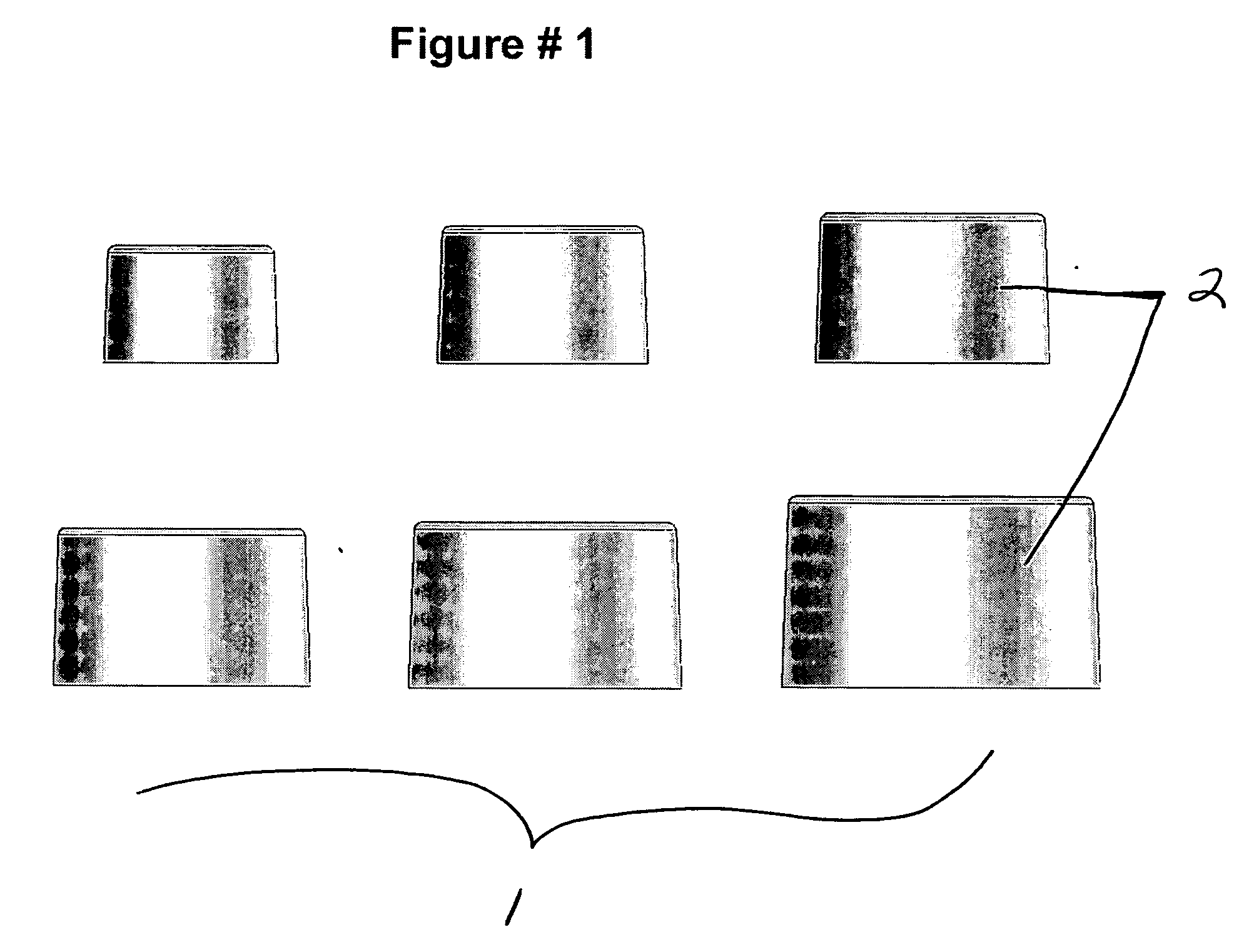
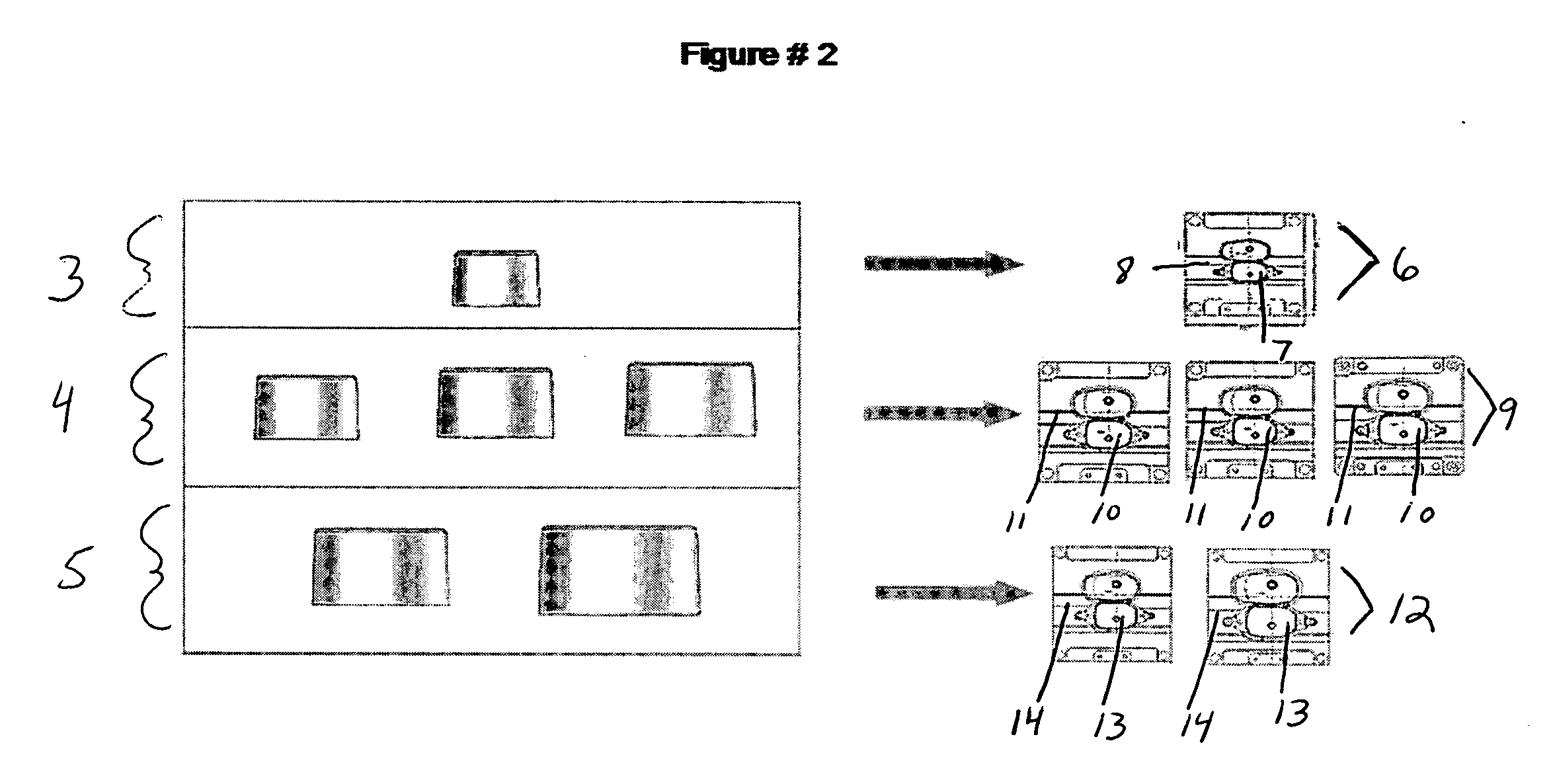
The present invention is directed to a modular mold system comprising at least two mold designs or mold sizes. In a further embodiment, the present invention is directed to a modular mold system comprising molds that are the same design but vary in size and cavitation. In a further embodiment, the present invention is directed toward a modular mold system for production of a family of a part designs. In a further embodiment, the present invention is directed toward a modular mold system developed from a part design and a part size. Another embodiment of the present invention would be directed toward a modular mold system comprising at least two mold sizes comprising standardized and identical components.

Description

CROSS REFERENCE TO RELATED APPLICATIONS [0001] This application claims the benefit of U.S. Provisional application Ser. No. 60 / 760,525, filed on Jan. 20, 2006.FIELD OF THE INVENTION [0002] The present invention relates to an optimized modular injection mold system developed for the production of product family designs or items similar in design but varying in size. This modular mold system comprises multiple mold designs and multiple mold insert designs, both optimized to the part design, the family of item sizes, and the item production needs. BACKGROUND OF THE INVENTION [0003] The present invention relates to an optimized modular injection mold system developed for the production of product family designs—or items similar in design but varying in size. This modular mold system comprises multiple mold designs and multiple mold insert designs, both optimized to the item design, the family of item sizes, and the item production needs. [0004] The primary concept of modular molds is to...

Claims


Application Information

Patent Timeline
IPC IPC(8): B29C45/10
CPCB29C45/2673B29C33/306
Inventor KERR, GEORGE SCOTTPEISCHL, GREGORY CHRISTOPHERARMBRUSTER, RAINER
Owner THE PROCTER & GAMBLE COMPANY
Learn More