Real time mesh measurement systen stream latency and jitter measurements

a real-time mesh and systen stream technology, applied in the field of real-time mesh measurement systen stream latency and jitter measurement, can solve the problem of general unsatisfactory efforts

Inactive Publication Date: 2008-01-03
INFRASTRUCTURE INNOVATIONS
View PDF22 Cites 30 Cited by
  • Summary
  • Abstract
  • Description
  • Claims
  • Application Information

AI Technical Summary

Benefits of technology

[0007] This ability to continually and simultaneously measure latency (both end-to-end and for each component) allows the measurement “sense” to identify the specific component that may be causing latency jitter that exceeds thresholds and cause intermittent business bandwidth problems. Additionally, the ability to synchronize measurements taken from multiple tools / end points (and correlate / analyze in real time this information) is what is referred to as the Real Time Mesh Measurement System.

Problems solved by technology

Although attempts have been made to determine latency and latency jitter through use of remote monitoring devices (RMONSs) and the like, such efforts have generally been unsatisfactory.

Method used


Image

  • Real time mesh measurement systen stream latency and jitter measurements
  • Real time mesh measurement systen stream latency and jitter measurements
  • Real time mesh measurement systen stream latency and jitter measurements

Examples


Embodiment Construction

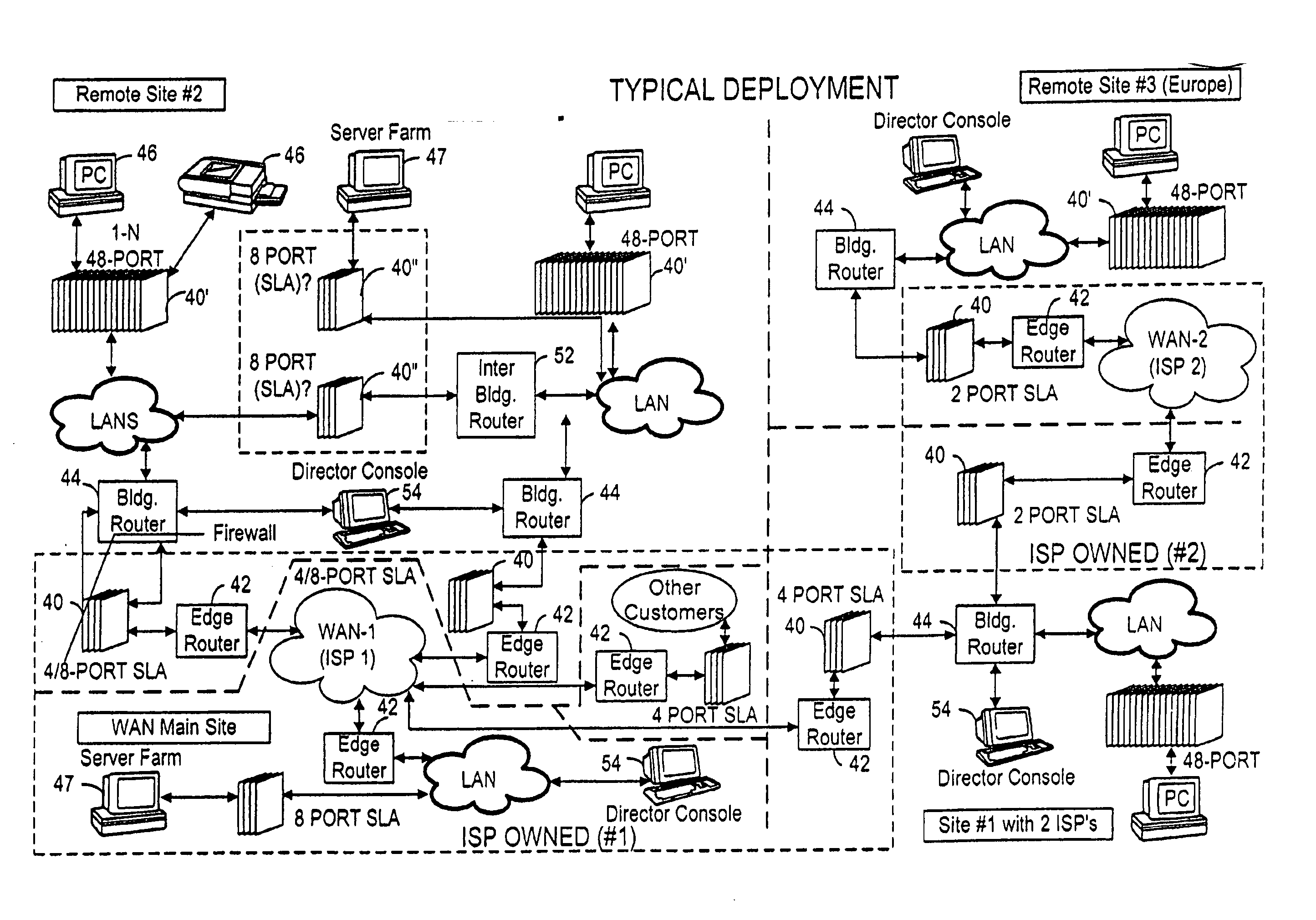
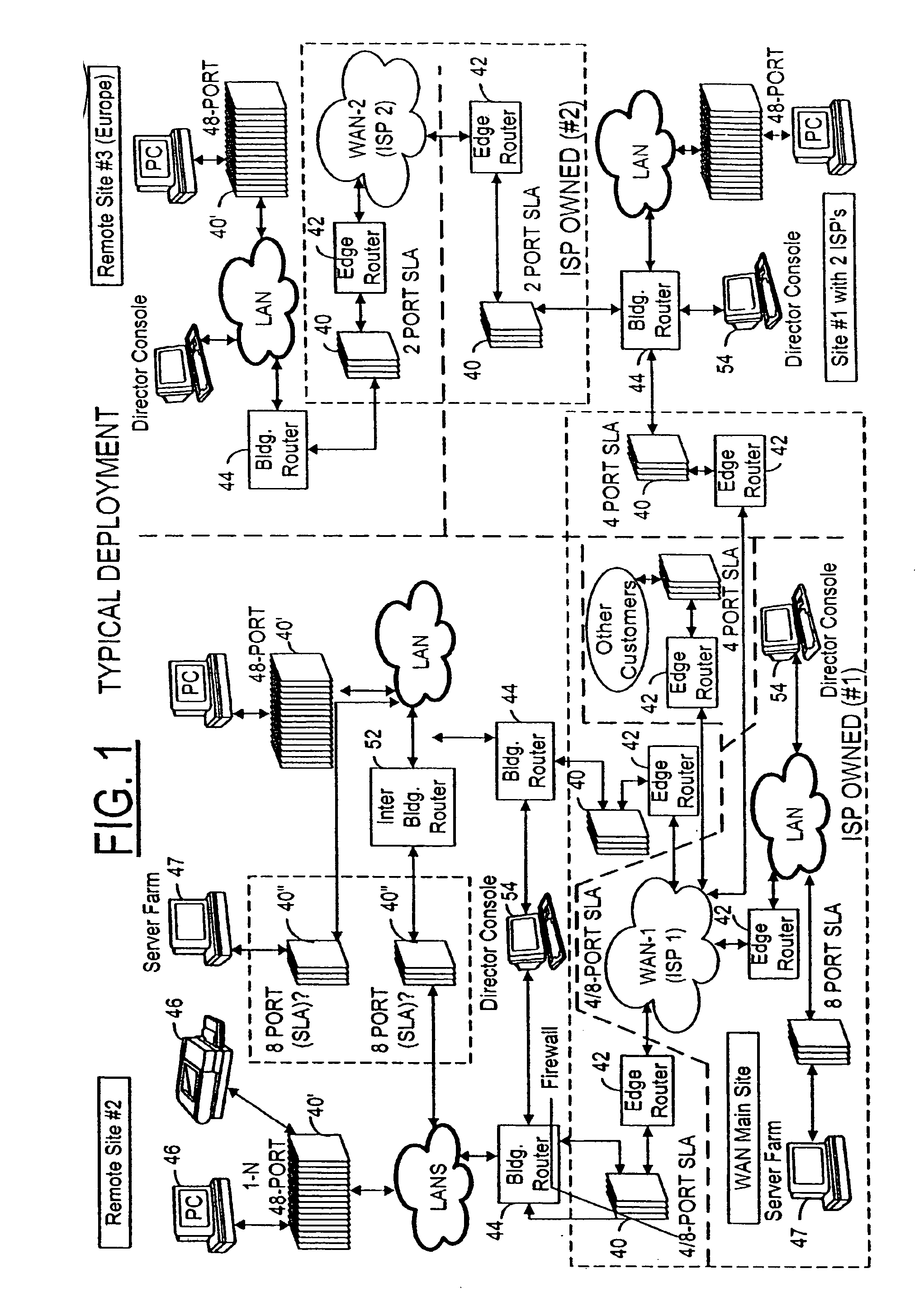
[0037] As best seen in FIG. 1, a typical deployment of the present invention comprises a plurality of bandwidth monitoring devices 40, such as edge devices which are typically co-located with edge routers 42 and building routers 44. Edge routers (switch fabric) are typically deployed at the edge of one wide area network (WAN) associated with an internet service provider (ISP) or between a WAN and a local area network (LAN) as shown in FIG. 1. The edge devices (appliances) (bandwidth monitoring devices at the edge of different networks) are positioned so as to monitor bandwidth passing through an edge router typically to a building router 44 from whence the bandwidth is communicated through LANs, ultimately to one or more network enabled devices 46 such as PCs, printers and the like and / or to server farms 47. Depending upon the level of monitoring, a special type of bandwidth monitoring device such as a network enabled device bandwidth monitoring device 40 particularly suited for con...


PUM


Abstract

A method is described for measuring system latency and latency jitter on a near real-time basis regarding packets of information moving from sources to destination. The method for measuring system latency and latency jitter includes time-stamping packets of information as they pass through a plurality of locations between the source and destination of these packets, with the time-stamping being performed by real-time clocks set to a universal standard. The time-stamped packets are analyzed to determine latency and latency jitter. The measurements of system latency and latency jitter can be performed based upon packet types so as to obtain accurate information concerning different types of business bandwidths associated with an observed network.

Description

CROSS REFERENCE TO RELATED APPLICATIONS [0001] This application is a continuation of U.S. patent application Ser. No. 10 / 222,211 filed on Aug. 16, 2002 and claims domestic priority to said application under 35 USC §120.TECHNICAL FIELD [0002] The present invention is directed to an implementation / method that identifies how to create a new measuring “sense” for measuring business bandwidth performance. This new “sense” is the ability to “see” (observe & measure) in real time business bandwidth latencies and the rate of change of the latency, known as latency jitter. BACKGROUND OF THE INVENTION [0003] In a networked environment, the length of time for packets to travel from a source to a destination can vary for many reasons, including delays due to routers, communication, media, and the like. Although attempts have been made to determine latency and latency jitter through use of remote monitoring devices (RMONSs) and the like, such efforts have generally been unsatisfactory. It is des...

Claims


Application Information

Patent Timeline
Patent Type & Authority Applications(United States)
IPC IPC(8): G06F15/173
CPCH04L41/5009H04L43/0858H04L65/80H04L43/106H04L43/087
Inventor KRYSKOW, JOSEPH M. JR.HUDNALL, RICHARD E.
Owner INFRASTRUCTURE INNOVATIONS
Why Eureka
Try Eureka