

Arm for moving flexible lines at a wellsite
- Summary
- Abstract
- Description
- Claims
- Application Information
AI Technical Summary
Benefits of technology
Problems solved by technology
Method used
Image

Examples
Embodiment Construction
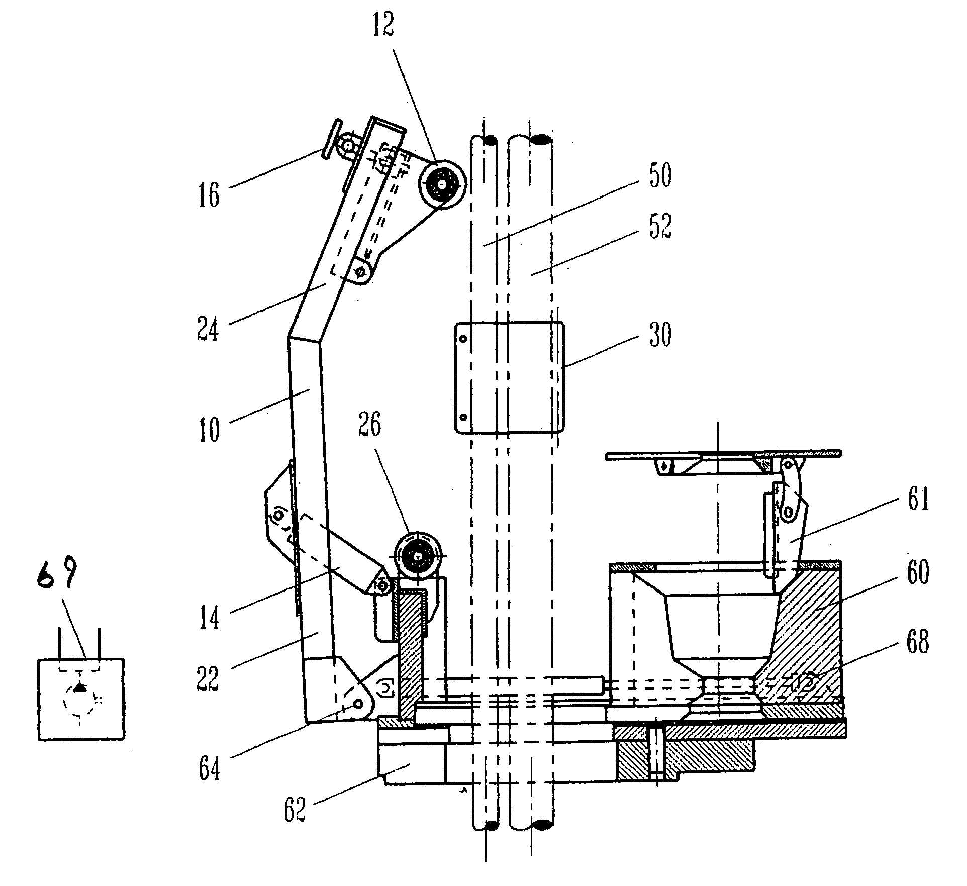
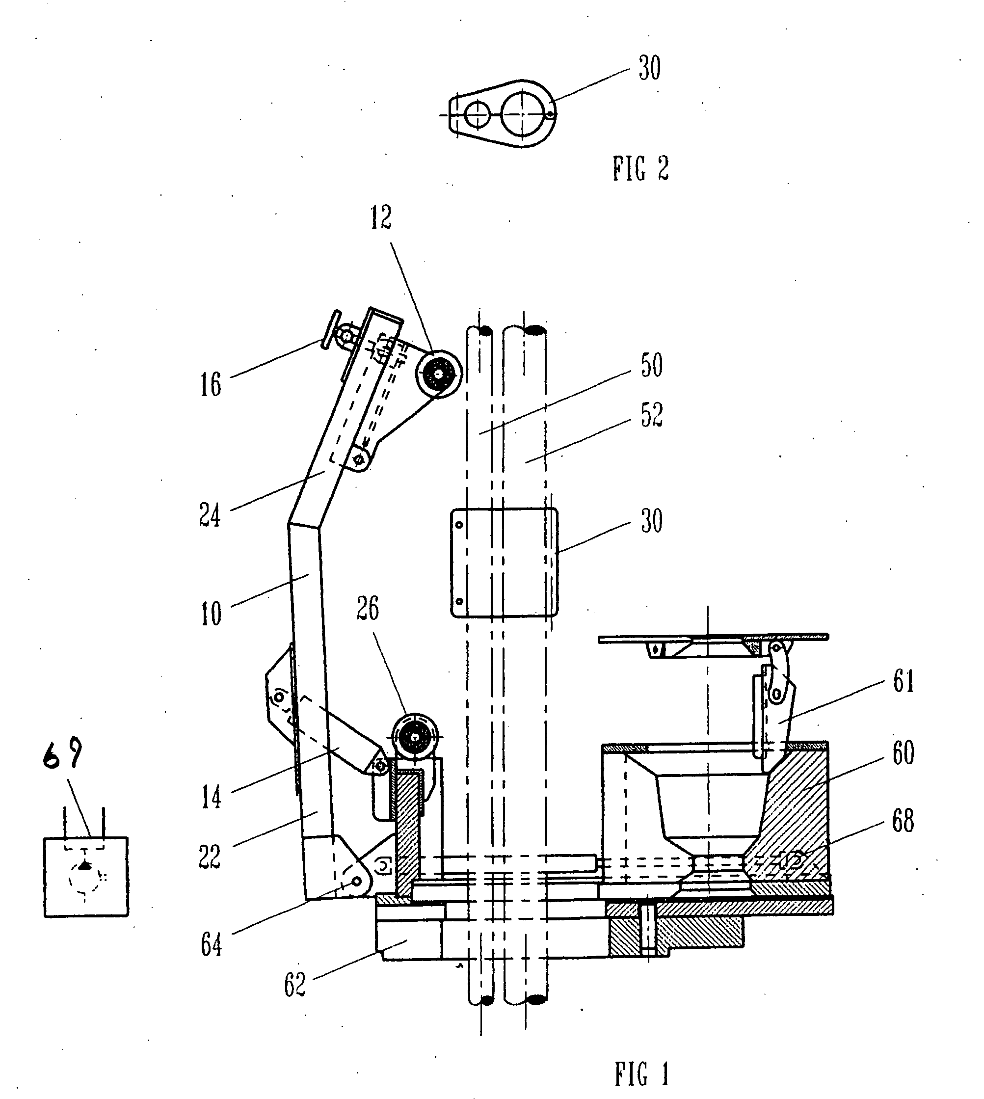
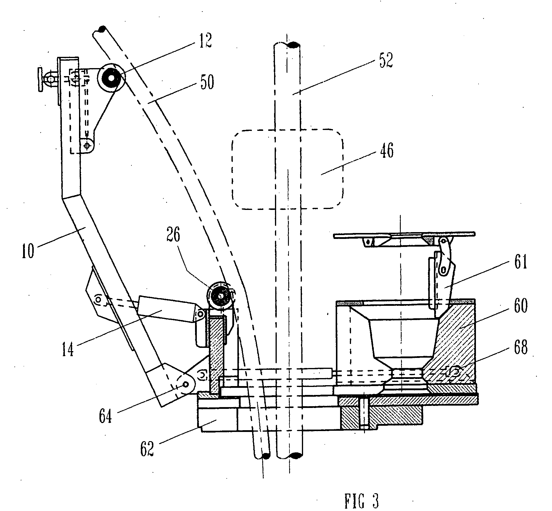
[0048]FIG. 1 depicts one embodiment of a moveable arm 10 engaging a flexible line 50 at a well site for positioning the line between a clamping position, as shown in FIG. 1, for clamping the flexible line to a tubular 52, and a run-in position, as shown in FIG. 3, wherein the flexible line is spaced from the tubular for allowing equipment to engage the tubular and to run the flexible line with the tubular into the well. As shown in FIG. 1, the moveable arm 10 extends upward from the rig floor on which the base or plate 62 of the slip bowl assembly 60 is positioned. Arm 10 includes a lower arm portion 22 which is pivotally connected at 64 to the base or plate 62 of the slip bowl assembly 60, and an upper arm portion 24 which is inclined or canted relative to lower arm portion 22. A roller 12 is pivotally mounted on the upper arm portion 24, and serves as a flexible line guide for engaging the flexible line 50 when in the run-in position. The adjustment mechanism 16 comprising a threa...
PUM
 Abstract
Description
Claims
Application Information