Non-Skin-Contacting Microneedle Array Applicator

a microneedle array and applicator technology, applied in the field of non-skin-contacting microneedle array applicators, can solve the problem of limited number of molecules with demonstrated, and achieve the effect of facilitating the transdermal delivery of therapeutic agents

Inactive Publication Date: 2008-01-10
3M INNOVATIVE PROPERTIES CO
View PDF2 Cites 168 Cited by
  • Summary
  • Abstract
  • Description
  • Claims
  • Application Information

AI Technical Summary

Problems solved by technology

Only a limited number of molecules with demonstrated therapeutic value can be transported through the skin, even with the use of approved chemical enhancers.

Method used


Image

  • Non-Skin-Contacting Microneedle Array Applicator
  • Non-Skin-Contacting Microneedle Array Applicator
  • Non-Skin-Contacting Microneedle Array Applicator

Examples


Embodiment Construction

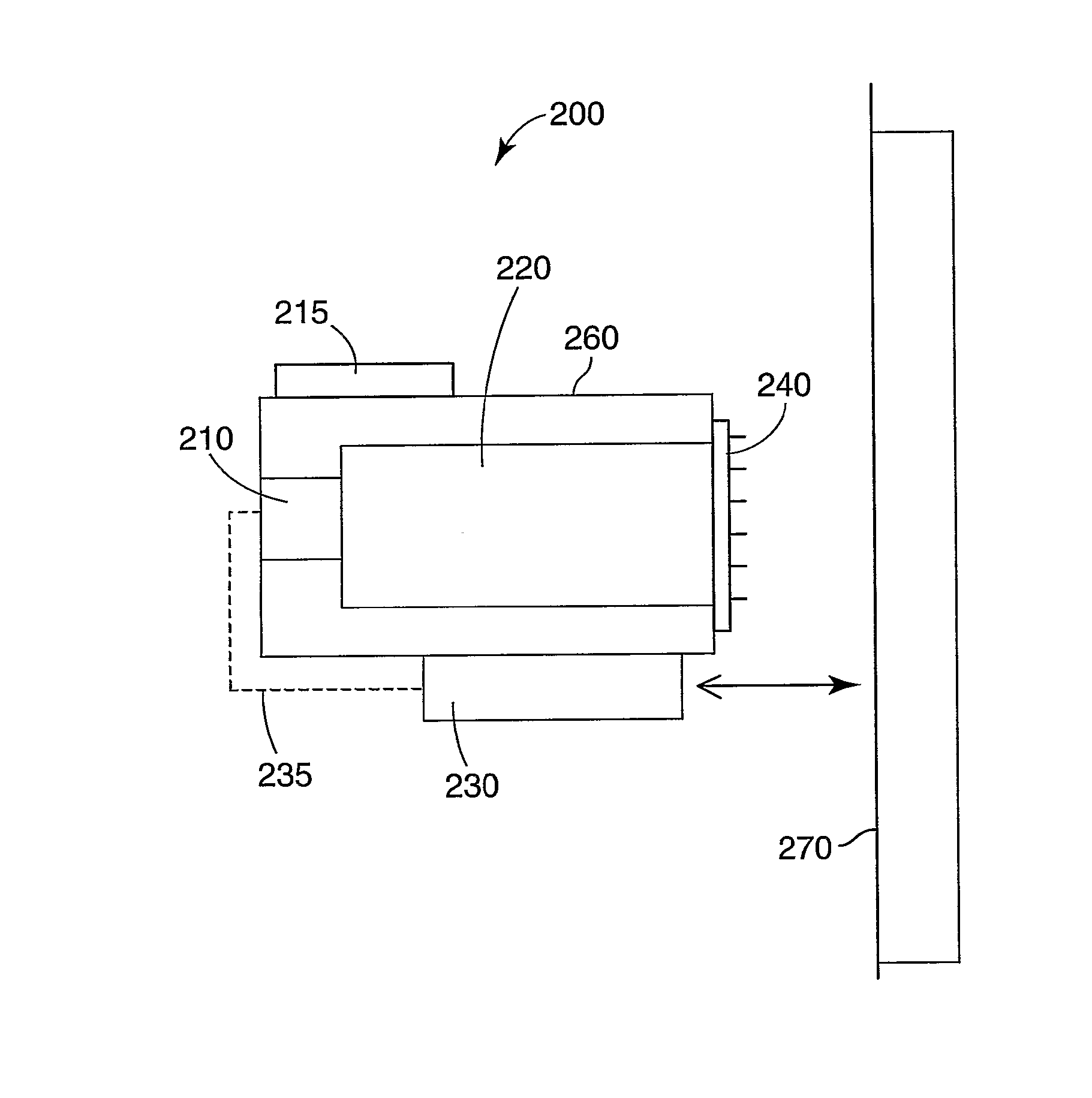
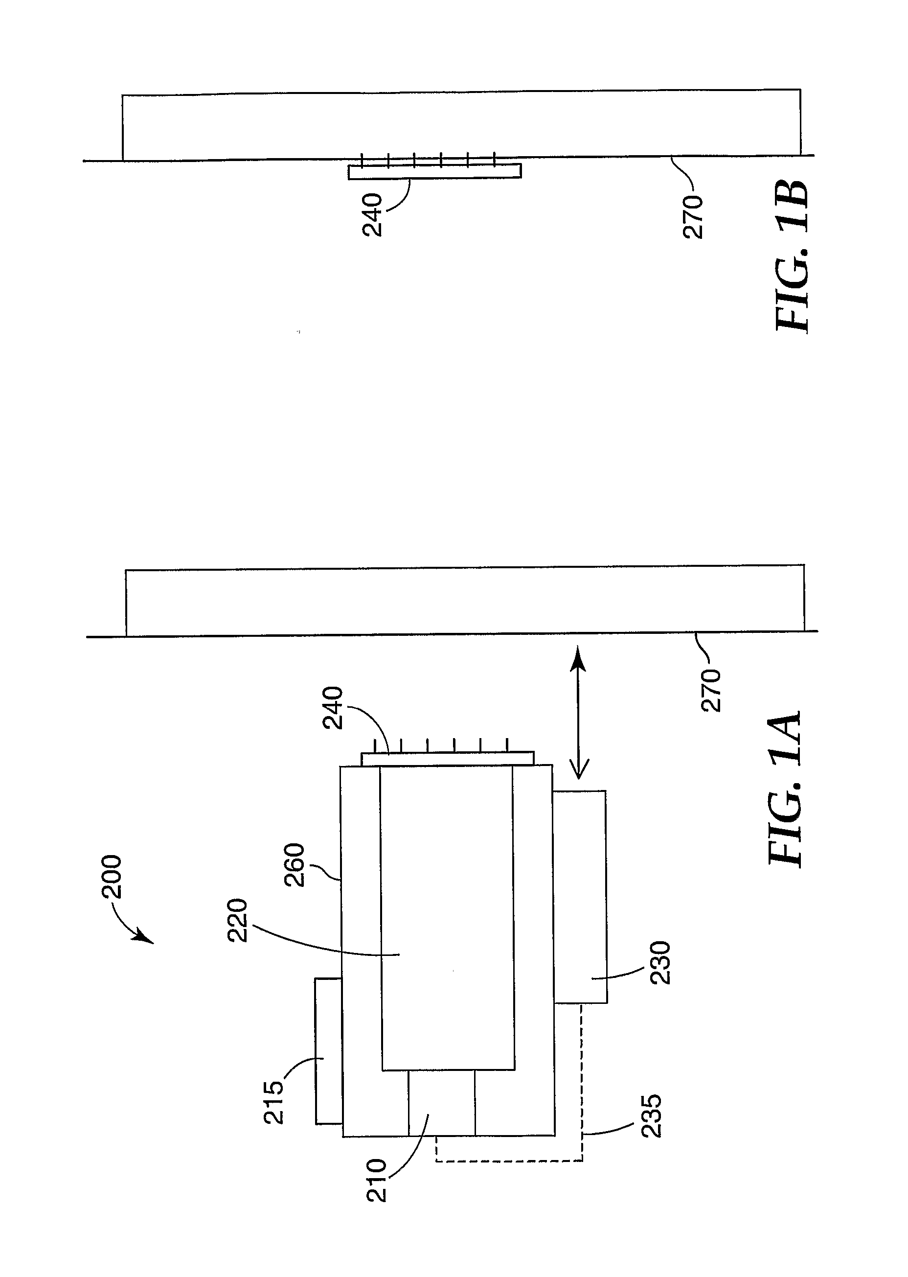
[0022] One embodiment of the microneedle application device is shown schematically in FIG. 1A. The application device 200 comprises a housing 260 that houses a piston 220 and a trigger release mechanism 210. The microneedle array 240 is releasably attached to the housing 260 by attachment means (not shown). A distance sensor 230 is connected to the outer part of the housing 260. The distance sensor is any suitable sensor capable of measuring the distance between the sensor and a remote object, such as a skin surface 270. The sensor 230 communicates with the trigger release 210 by a controller 235.

[0023] In operation, the trigger 215 is incapable of firing the piston 220 unless the trigger release mechanism 210 is receiving input from the sensor 230 indicating that the sensor 230 is within a predetermined range of distance from a target surface. Thus, the trigger release mechanism 210 serves as both a safety mechanism and a positioning mechanism to prevent the trigger 215 from firin...


PUM


Abstract

An applicator used to apply microneedle arrays to a mammal. An applicator capable of sensing a controlled distance from a skin surface and propelling a microneedle array across this distance and into the skin surface is disclosed. A method of applying a microneedle array to a skin surface by placing the microneedle array a predetermined distance away from the skin surface and propelling the microneedle array into the skin surface is disclosed.

Description

CROSS-REFERENCE TO RELATED APPLICATIONS [0001] The present application claims priority to U.S. Provisional Application Serial No. 60 / 629,186, filed on Nov. 18, 2004, which is incorporated herein in its entirety.FIELD [0002] The present invention relates to applicators used to apply microneedle arrays to a mammal. The present method also relates to methods of applying a microneedle array or patch to a mammal. BACKGROUND [0003] Only a limited number of molecules with demonstrated therapeutic value can be transported through the skin, even with the use of approved chemical enhancers. The main barrier to transport of molecules through the skin is the stratum comeum (the outermost layer of the skin). [0004] Devices including arrays of relatively small structures, sometimes referred to as microneedles or micro-pins, have been disclosed for use in connection with the delivery of therapeutic agents and other substances through the skin and other surfaces. The devices are typically pressed a...

Claims


Application Information

Patent Timeline
Patent Type & Authority Applications(United States)
IPC IPC(8): A61M5/158
CPCA61B17/205A61M2037/0023A61M37/0015
Inventor CANTOR, ADAM S.
Owner 3M INNOVATIVE PROPERTIES CO
Why Eureka
Try Eureka