Apparatus and method for ignition timing for small gasoline engine

a technology for gasoline engines and ignition timing, applied in the direction of electric ignition installation, engine ignition, generator generated ignition energy, etc., can solve the problem of limited opportunity to start the engine, and achieve the effect of increasing the likelihood of spark firing

Inactive Publication Date: 2008-01-17
PHELON EURO
View PDF15 Cites 7 Cited by
  • Summary
  • Abstract
  • Description
  • Claims
  • Application Information

AI Technical Summary

Benefits of technology

[0009] In another aspect, the present invention provides an ignition timing technique for use during cranking. During cranking, especially with pull-started engines, there is limited opportunity to start the engine. The present invention provides an ignition timing technique which increases the likelihood of spark firing by obtaining speed information using only a portion of the first revolution. Irregularity in engine speed while cranking is also determined during the first revolution. After acquiring the speed information, the appropriate spark delay time is determined.

Problems solved by technology

During cranking, especially with pull-started engines, there is limited opportunity to start the engine.

Method used


Image

  • Apparatus and method for ignition timing for small gasoline engine
  • Apparatus and method for ignition timing for small gasoline engine
  • Apparatus and method for ignition timing for small gasoline engine

Examples


Embodiment Construction

[0018] Reference will now be made in detail to presently preferred embodiments of the invention, one or more examples of which are illustrated in the accompanying drawings. Each example is provided by way of explanation of the invention, not limitation of the invention. In fact, it will be apparent to those skilled in the art that modifications and variations can be made in the present invention without departing from the scope or spirit thereof. For instance, features illustrated or described as part of one embodiment may be used on another embodiment to yield a still further embodiment. Thus, it is intended that the present invention covers such modifications and variations.

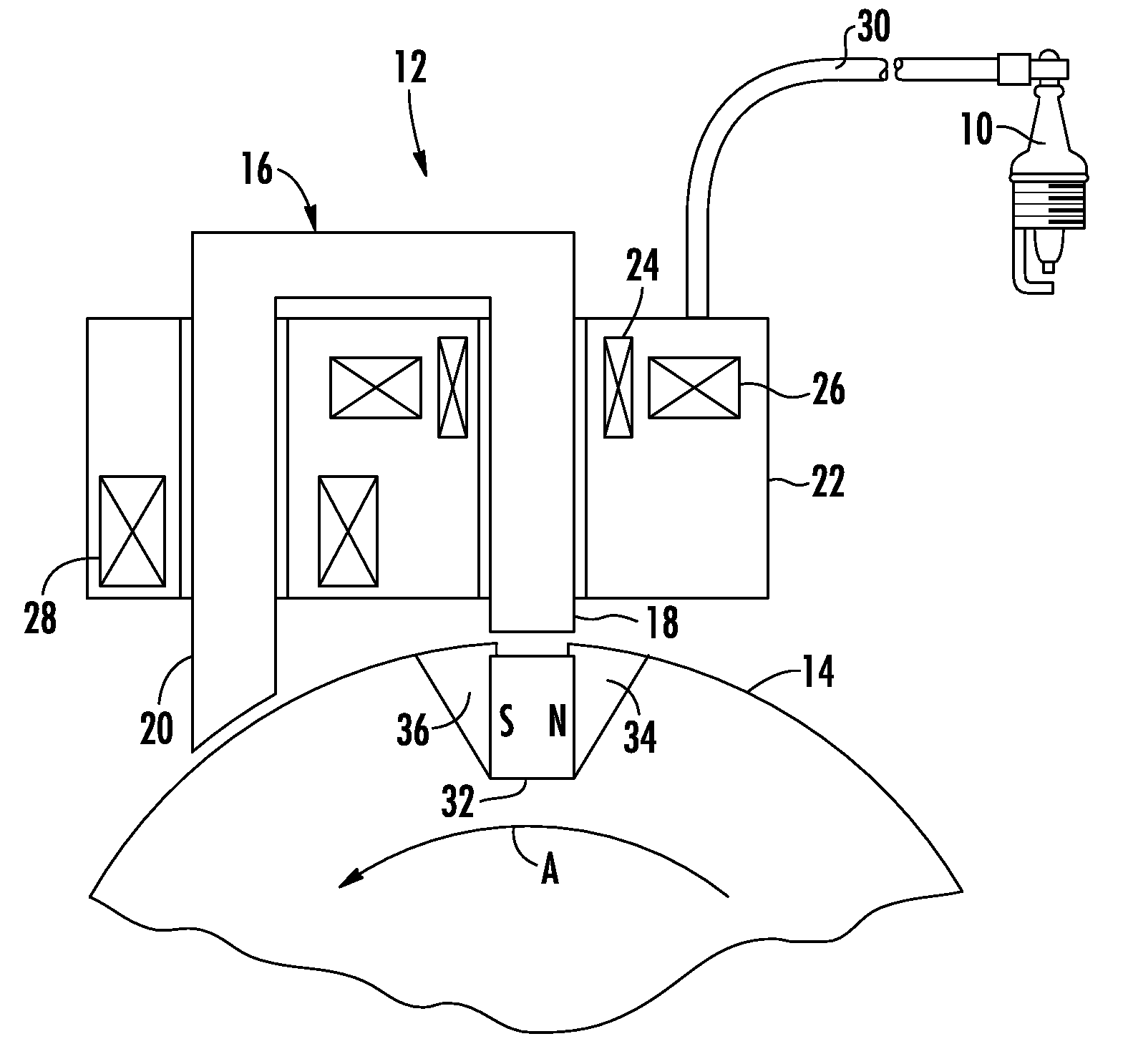
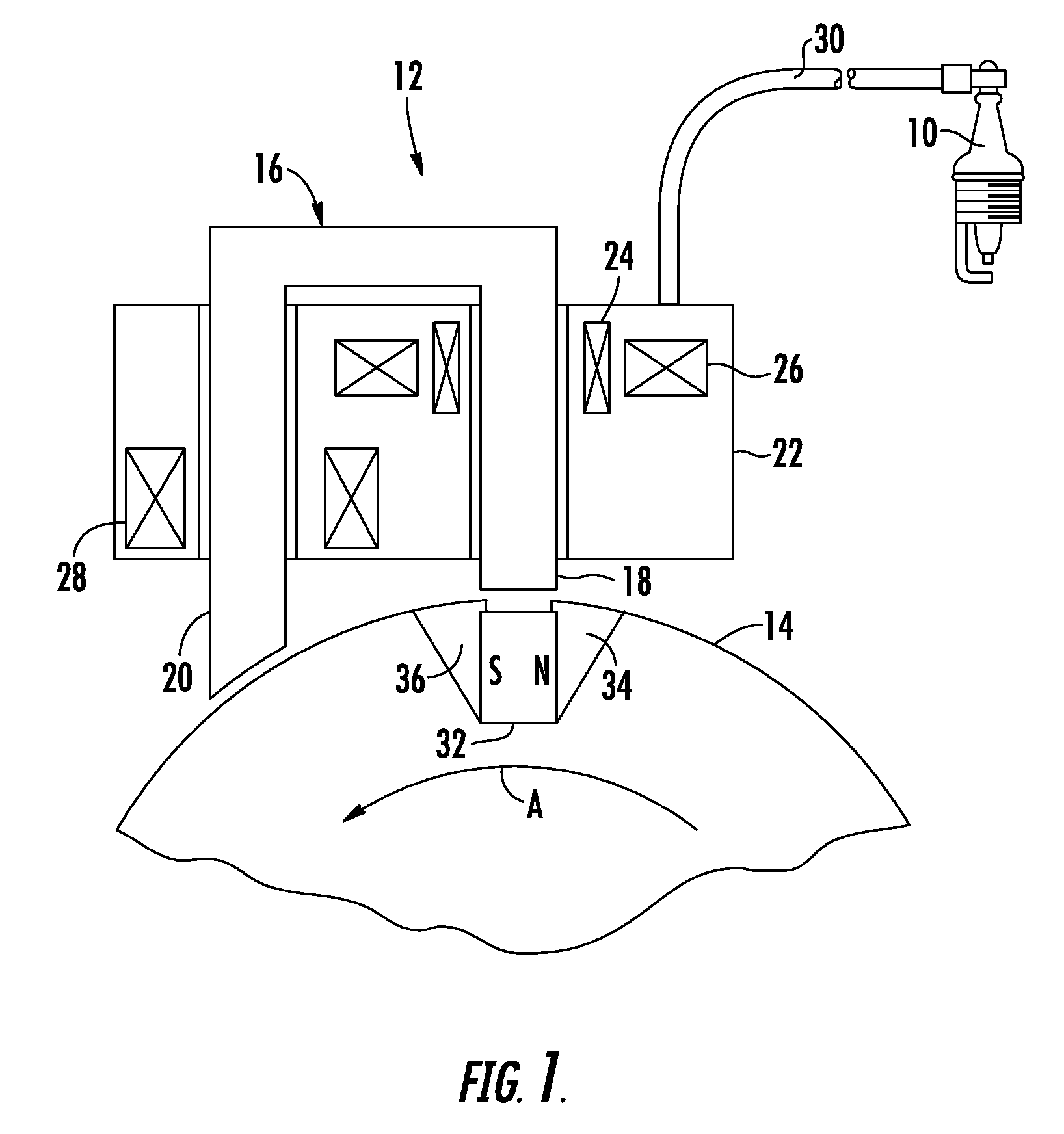
[0019]FIG. 1 illustrates a discharge ignition apparatus that may be used with various devices powered by gasoline engines. The apparatus is configured to produce the requisite spark at spark plug 10 to ignite the air-fuel mixture within the piston cylinder of the engine. Generally, the apparatus includes a sta...


PUM


Abstract

An apparatus and method for use with an internal combusting engine that accurately control ignition timing. Reference signals are created which are used to determine both the mean engine speed as well as irregular speed. Control logic uses this engine information to accurately predict the future rotational position of the engine. The ignition timing is then adjusted to release the spark at the appropriate time.

Description

PRIORITY CLAIM [0001] This application claims the benefit of provisional application Ser. No. 60 / 830,298, filed Jul. 12, 2006, which is relied upon and incorporated herein by reference.BACKGROUND OF THE INVENTION [0002] The present invention generally relates to an ignition timing system for small gasoline engines. More particularly, the invention relates to an apparatus and method for controlling the ignition timing by utilizing at least one reference signal per engine revolution. The at least one reference signal is preferably used to determine the mean speed of the engine as well as irregular engine speed. By controlling the ignition system by considering both mean speed and irregular speed, such as deceleration, ignition timing accuracy can be increased. [0003] It is well known to use an analog ignition system with RPM timing control. When a magnet located on a flywheel passes a coil, a voltage spike is induced that is proportional to engine speed. This voltage spike is relative...

Claims


Application Information

Patent Timeline
Patent Type & Authority Applications(United States)
IPC IPC(8): F02P5/145
CPCF02P1/086F02P5/1506Y02T10/46F02P7/067F02P5/1551Y02T10/40
Inventor BENGTSSON, JORGENSTYRBJORN, GRENGUSTAFSSON, BERT
Owner PHELON EURO
Why Eureka
Try Eureka