Magnetron for cylindrical targets

a magnetron and cylindrical technology, applied in the direction of vacuum evaporation coating, electric discharge tube, coating, etc., can solve the problems of extreme local heating of various components, increased complexity and cost in the design and arrangement of hardware, and insufficient utilization of the target material to be sputtered from, etc., to achieve the effect of not adding highly incremental costs to the overall design of the electrod

Active Publication Date: 2008-01-17
ANGSTROM SCI
View PDF10 Cites 31 Cited by
  • Summary
  • Abstract
  • Description
  • Claims
  • Application Information

AI Technical Summary

Benefits of technology

[0010] The present invention also provides for rotatable cylindrical magnetron sputtering device that includes the electrode of the present invention and a drive assembly in communication with the cathode body and the cylindrical target, wherein the drive assembly. comprises a drive shaft and a motor and,

Problems solved by technology

A problem with the conventional planar magnet arrangement is that the magnets have flat upper surfaces and, therefore, the target which the material is to be sputtered from is not completely utilized.
Although enabling power supply technology has increased process stability of the deposition process, it has simultaneously introduced increased complexity and cost into the design and arrangement of the hardware associated with the cathode drive assembly which delivers this power to the target surface.
The two most common problems associated with the delivery of high power, mid-frequency (20 kHz-120 kHz) current to the cathode are (1) t

Method used


Image

  • Magnetron for cylindrical targets
  • Magnetron for cylindrical targets
  • Magnetron for cylindrical targets

Examples


Embodiment Construction

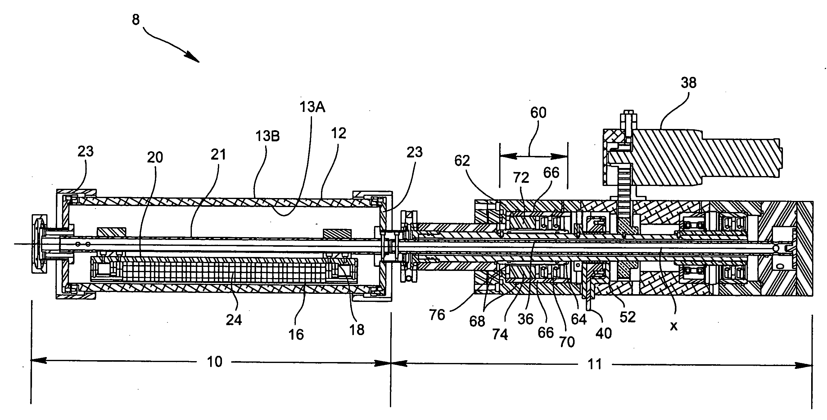
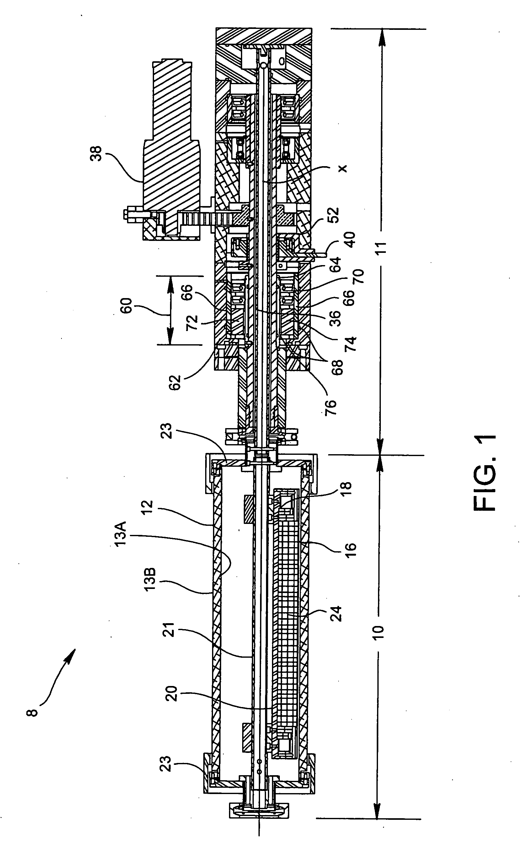
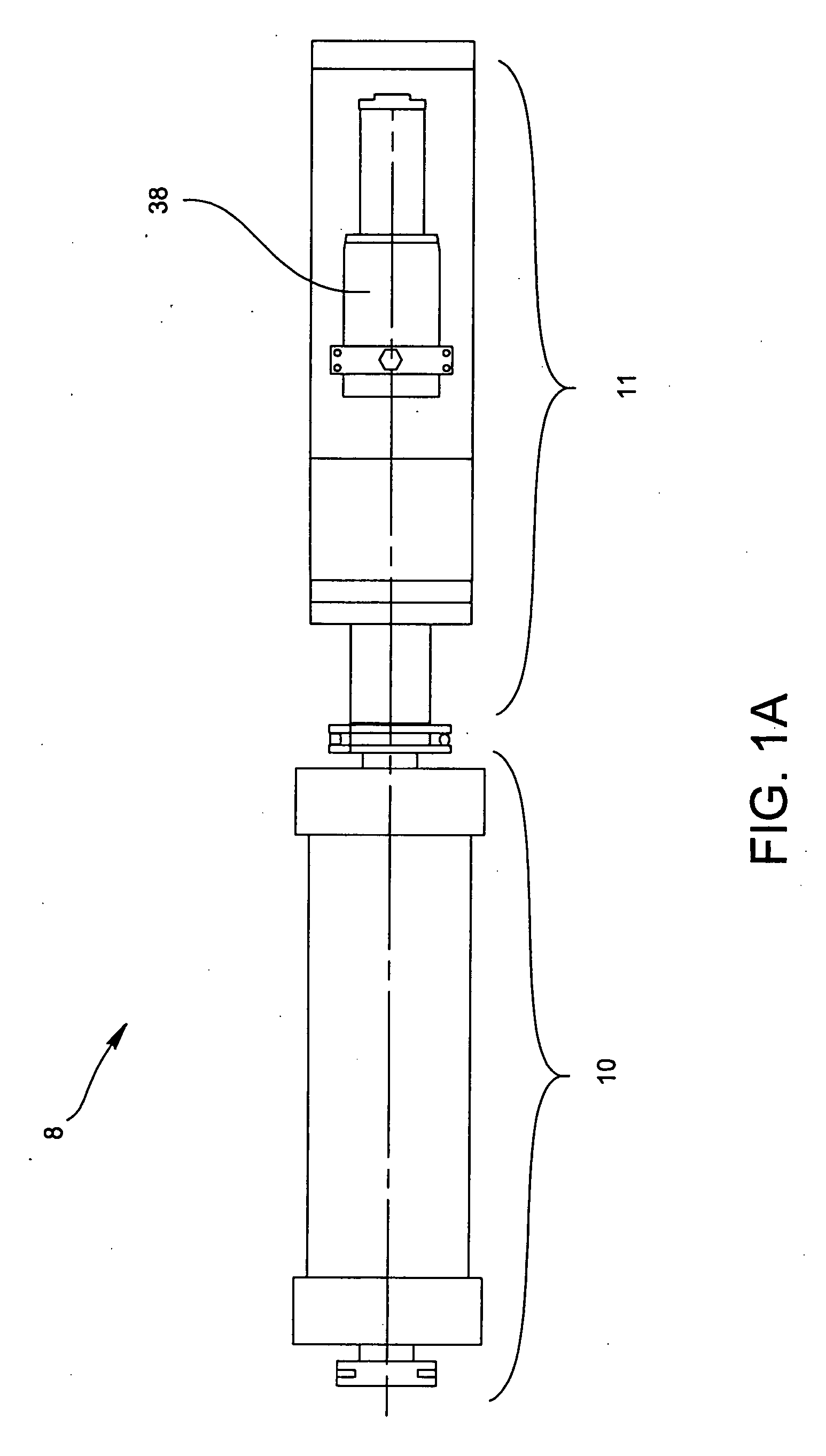
[0019] The present invention provides for a rotatable cylindrical magnetron sputtering device 8 that includes an electrode 10 and a drive assembly 11 attached to the electrode 10 as shown in FIGS. 1 and 1A. Referring to FIGS. 1 and 2, the electrode 10 includes a hollow cylindrical target 12 having an inner surface 13A and an outer surface 13B, a cathode body 14 having a first surface 16 and a second surface 18 received within the cylindrical target 12, a base plate 20 attached to the second surface 18 of the cathode body 14 and a central member 21 such as a shaft or sleeve received within the cylindrical target 12 and attached to the base plate 20 for supporting the cathode body 14, wherein the cylindrical target 12 is rotatable about the cathode body 14 as shown as arrow Z in FIG. 2 about the longitudinal axis X. Referring back to FIG. 1, the cylindrical target 12 is held in place by an annular target retaining member 23, which is in communication with the drive assembly 11. Attach...


PUM

PropertyMeasurementUnit
Currentaaaaaaaaaa
Electrical conductoraaaaaaaaaa
Electric potential / voltageaaaaaaaaaa

Abstract

A magnet arrangement which is usable as both a retrofit magnetic arrangement in a rotatable cylindrical magnetron sputtering electrode as well as a drive assembly in communication with the electrode for delivering high current into a target surface without adding highly incremental cost to the overall design of the electrode. The electrode includes a cathode body defining a magnet receiving chamber, a rotatable cylindrical target surrounding the cathode body, wherein the target is rotatable about the cathode body. The cathode body further defines a magnet arrangement received within the magnet receiving chamber, wherein the magnet arrangement comprised of a plurality of magnets wherein at least one of the magnets is a profiled magnet having a contoured top portion.

Description

CROSS REFERENCE TO RELATED APPLICATIONS [0001] This application claims the benefit of U.S. Provisional Application Nos. 60 / 783,689 entitled “Magnetron For Cylindrical Targets” filed on Mar. 17, 2006, and 60 / 859,393 entitled “Magnetron For Cylindrical Targets And Cathode Design Enhancements” filed on Nov. 16, 2006, which are hereby incorporated by reference.BACKGROUND OF THE INVENTION [0002] 1. Field of the Invention [0003] The present invention relates to a rotatable cylindrical magnetron sputtering apparatus and, more particularly, to a various hardware used with rotatable cylindrical magnetron electrodes which reduce the cost and complexity of delivering high power AC current into a target surface, and increase the target utilization and the deposition rate while reducing the amount of target material on the chamber walls and shielding. [0004] 2. Description of Related Art [0005] A typical magnetron sputtering device includes a vacuum chamber having an electrode contained therein,...

Claims


Application Information

Patent Timeline
IPC IPC(8): H05H13/00
CPCH01J37/3452H01J37/3405C23C14/3407C23C14/35
Inventor BERNICK, MARK A.NEWCOMB, RICHARD
Owner ANGSTROM SCI
Why Eureka
Try Eureka