Cylindrical magnetron having a shunt

a cylindrical magnetron and cylindrical technology, applied in the direction of electrolysis components, vacuum evaporation coatings, coatings, etc., can solve the problems of extreme local heating of various components, increased complexity and cost in the design and arrangement of hardware, and insufficient utilization of the target material to be sputtered from, etc., to achieve the effect of not adding highly incremental costs to the overall design of the electrod

Active Publication Date: 2015-02-10
ANGSTROM SCI
View PDF26 Cites 6 Cited by
  • Summary
  • Abstract
  • Description
  • Claims
  • Application Information

AI Technical Summary

Benefits of technology

[0011]The present invention also provides for a rotatable cylindrical magnetron sputtering device that includes the electrode of the present invention and a drive assembly in communication with the cathode body and the cylindrical target, wherein the drive assembly comprises a drive shaft and a motor and, wherein the drive shaft is rotatably connected to the cylindrical target. The drive assembly is adapted to rotate the cylindrical target and to introduce high current AC power into the target surface via the rotating drive shaft without adding highly incremental costs to the overall design of the electrode.

Problems solved by technology

A problem with the conventional planar magnet arrangement is that the magnets have flat upper surfaces and, therefore, the target which the material is to be sputtered from is not completely utilized.
Although enabling power supply technology has increased process stability of the deposition process, it has simultaneously introduced increased complexity and cost into the design and arrangement of the hardware associated with the cathode drive assembly which delivers this power to the target surface.
The two most common problems associated with the delivery of high power, mid-frequency (20 kHz-120 kHz) current to the cathode are (1) the ability of the brush assemblies to carry sufficient current without overheating and eroding due to the “skin-effect” of these frequencies and (2) the inherent eddy current effects induced by these frequencies which can cause extreme localized heating of various components, particularly the support bearing.
The design and manufacture of custom brushes used in these assemblies are not only costly, but the material is very brittle which can lead to a short operating life.
For example, one such solution for addressing the eddy current problem is to use a custom designed ceramic bearing, which is costly and difficult to replace quickly.
Such influences may include vacuum system irregularities such as non-uniform anode distribution and non-uniform system pumping or gas flow across the length of the target.
Such methods of fine tuning the sputtering have some limitations, however.
For example, raising and lowering the magnets only allows for tuning on the scale of the fixed lengths of the magnets, and may not permit for finer tuning on a smaller scale.

Method used


Image

  • Cylindrical magnetron having a shunt
  • Cylindrical magnetron having a shunt
  • Cylindrical magnetron having a shunt

Examples


Embodiment Construction

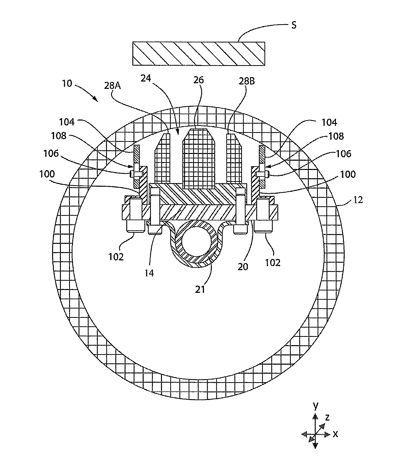
[0030]For purposes of the description hereinafter, the terms “end”, “upper”, “lower”, “right”, “left”, “vertical”, “horizontal”, “top”, “bottom”, “lateral”, “longitudinal” and derivatives thereof shall relate to the invention as it is oriented in the drawing figures. However, it is to be understood that the invention may assume various alternative variations and step sequences, except where expressly specified to the contrary. It is also to be understood that the specific devices and processes illustrated in the attached drawings, and described in the following specification, are simply exemplary embodiments of the invention. Hence, specific dimensions and other physical characteristics related to the embodiments disclosed herein are not to be considered as limiting. Further, it is to be understood that the invention may assume various alternative variations and step sequences, except where expressly specified to the contrary.

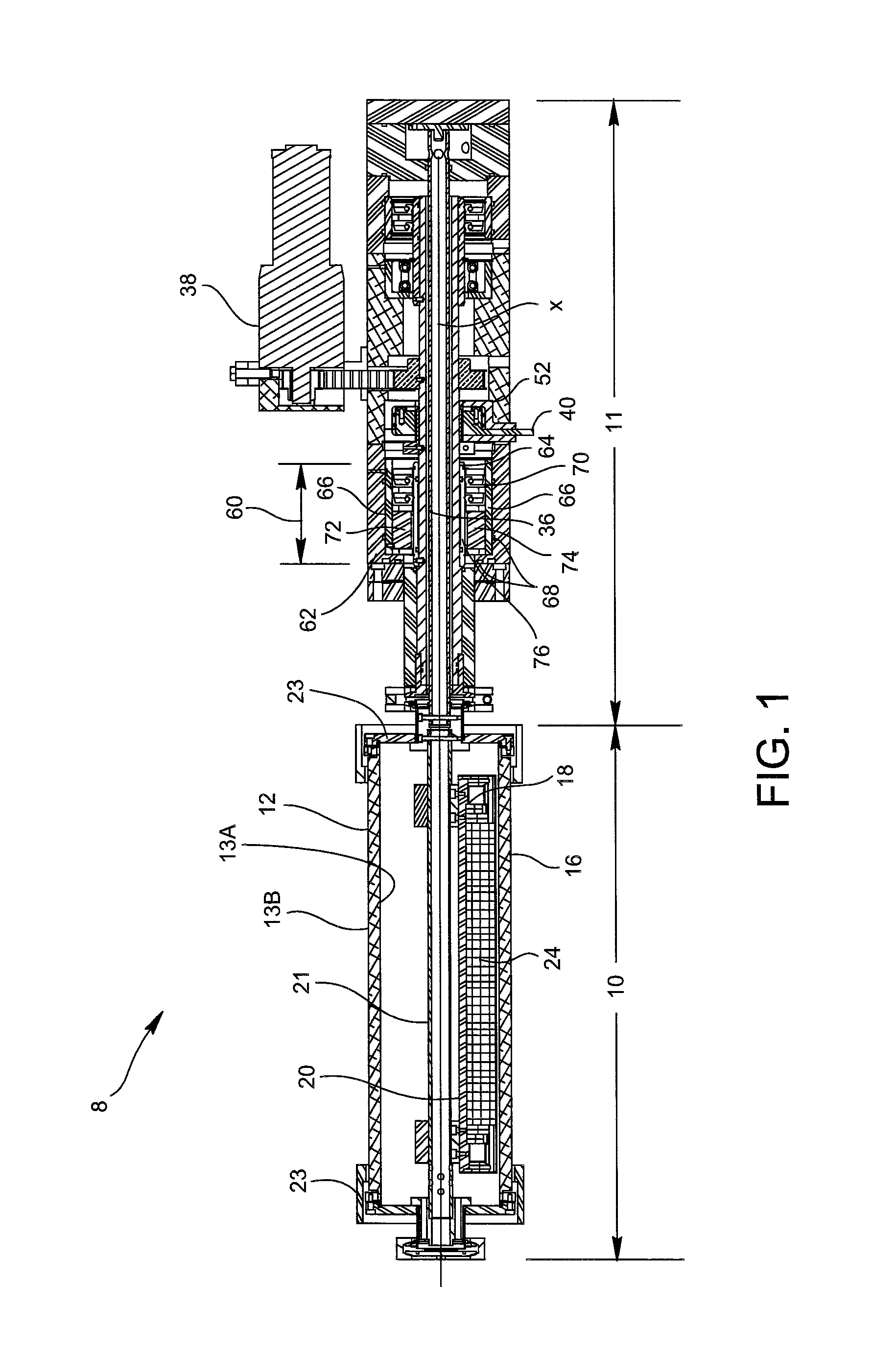
[0031]The present invention provides for a rotatable cyli...


PUM

PropertyMeasurementUnit
thicknessaaaaaaaaaa
angleaaaaaaaaaa
angleaaaaaaaaaa

Abstract

A magnetron sputtering electrode for use in a rotatable cylindrical magnetron sputtering device, the electrode including a cathode body defining a magnet receiving chamber and a cylindrical target surrounding the cathode body. The target is rotatable about the cathode body A magnet arrangement is received within the magnet receiving chamber, the magnet arrangement including a plurality of magnets. A shunt is secured to the cathode body and proximate to a side of the magnet arrangement, the shunt extending in a plane substantially parallel to the side of the magnet arrangement. A method of fine-tuning a magnetron sputtering electrode in a rotatable cylindrical magnetron sputtering device is also disclosed.

Description

CROSS-REFERENCE TO RELATED APPLICATIONS[0001]This application claims the benefit of U.S. Provisional Application No. 61 / 299,669, filed Jan. 29, 2010.BACKGROUND OF THE INVENTION[0002]1. Field of the Invention[0003]The present invention relates to a rotatable cylindrical magnetron sputtering apparatus having a shunt for fine-tuning the magnetic field.[0004]2. Description of Related Art[0005]A typical magnetron sputtering device includes a vacuum chamber having an electrode contained therein, wherein the electrode includes a cathode portion, an anode portion and a target. The term electrode is oftentimes referred to in the industry as a cathode. In operation, a vacuum is drawn in the vacuum chamber followed by the introduction of a process gas into the chamber. Electrical power supplied to the electrode produces an electronic discharge which ionizes the process gas and produces charged gaseous ions from the atoms of the process gas. The ions are accelerated and retained within a magnet...

Claims


Application Information

Patent Timeline
Patent Type & Authority Patents(United States)
IPC IPC(8): C23C14/00C25B13/00C25B11/00C23C14/35C23C14/54
CPCC23C14/35C23C14/54H01J37/3461C23C14/3407H01J37/3423H01J37/3435H01J37/345H01J37/347H01J2237/3323Y10T29/49002
Inventor BERNICK, MARK A.NEWCOMB, RICHARD
Owner ANGSTROM SCI
Why Eureka
Try Eureka