
Self-testing circuit interrupting device

a self-testing, circuit-based technology, applied in emergency protective arrangements, electrical appliances, emergency protection arrangements for limiting excess voltage/current, etc., can solve problems such as mechanical breakage of circuits, tripping of devices, surge of electricity, etc., to reduce contact landing bounce, facilitate very brief disconnect times, and increase the closing force

Active Publication Date: 2008-01-17
LEVITON MFG
View PDF98 Cites 49 Cited by
  • Summary
  • Abstract
  • Description
  • Claims
  • Application Information

AI Technical Summary

Benefits of technology

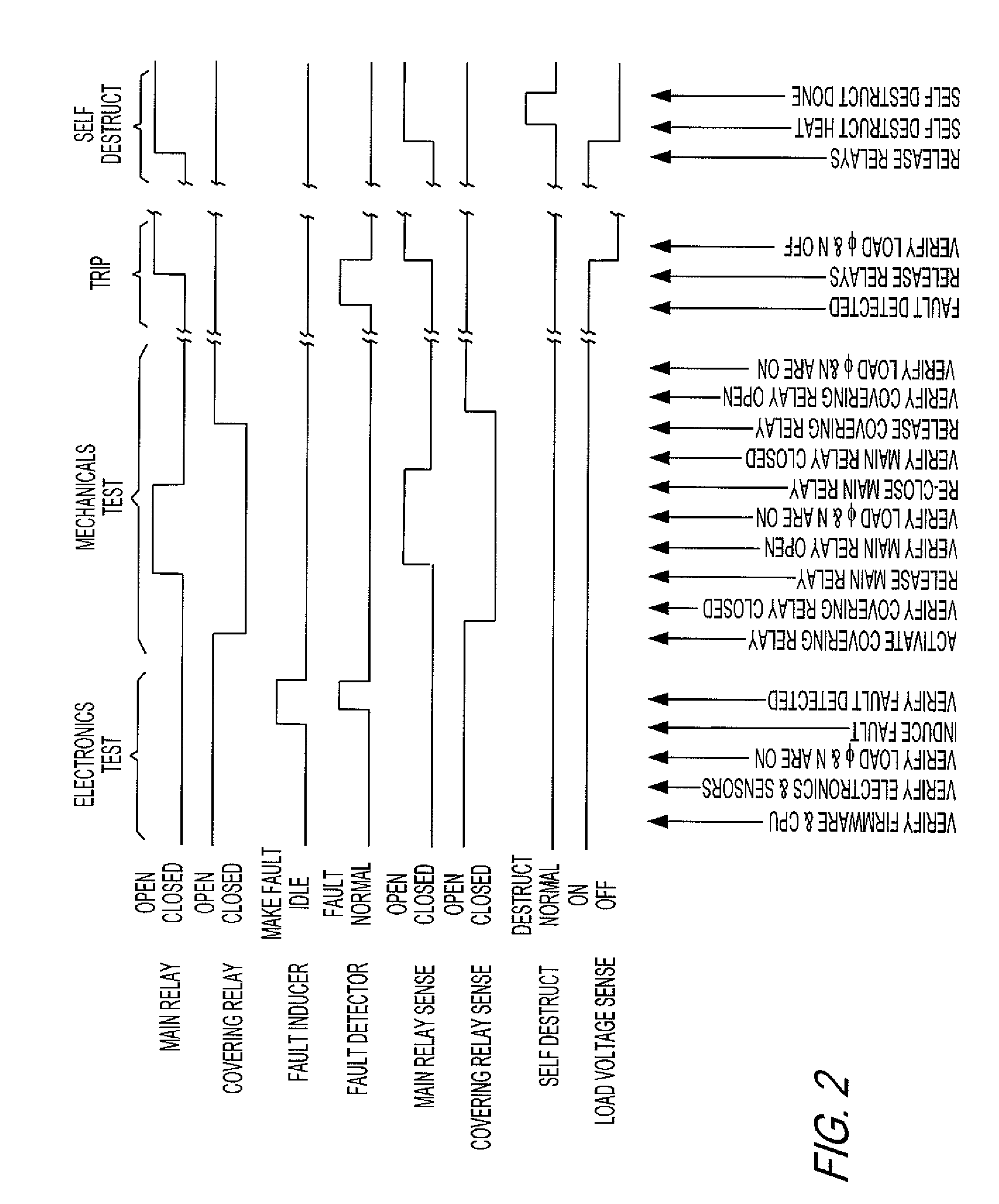
[0013] The time delay between electronic activation of the relay and its eventual movement may be design characterized, factory calibrated, and / or automatically adaptively adjusted after installation. Together with a power line voltage zero cross detection circuit, relay movement timing can be precisely controlled to occur proximate to the zero cross. Damping means may be employed to reduce contact landing bounce.
[0016] It is to be noted that a continuously held relay at its near closed position may require a much greater closing force to be applied than the opening force that is required. This difference facilitates very brief disconnect times. Also, it should be noted that regardless of the style of relay used, relay electromechanical characteristics may require that the reconnect signal be applied to the relay even before the disconnect signal has caused a disconnect.
[0017] The time delay between electronic activation of the relay and its eventual movement may be design characterized, factory calibrated, and / or automatically adaptively adjusted after installation. Together with a power line voltage zero cross detection circuit, relay movement timing is precisely controlled to occur proximate to the zero cross. Damping means may be employed to reduce contact landing bounce.

Problems solved by technology

However, instances may arise where an abnormal condition, caused by for example a lightening strike, occurs which may result not only in a surge of electricity at the device and a tripping of the device but also a disabling of the trip mechanism used to cause the mechanical breaking of the circuit.
Under such circumstances an unknowing user, faced with a GFCI which has tripped, may press the reset button which, in turn, will cause the device with an inoperative trip mechanism to be reset without the fault protection available.
This is not only impracticable for a home owner, but a very expensive, time consuming and difficult procedure in a building such as a hotel or large motel where each unit has a bathroom that is equipped with a GFCI which must be tested.

Method used


Image

  • Self-testing circuit interrupting device
  • Self-testing circuit interrupting device
  • Self-testing circuit interrupting device

Examples


Embodiment Construction

[0028] The present invention relates to resettable circuit interrupting devices, such as but not limited to GFCI devices that performs autonomous periodic automated self testing without interrupting power to a connected load if the test is passed.

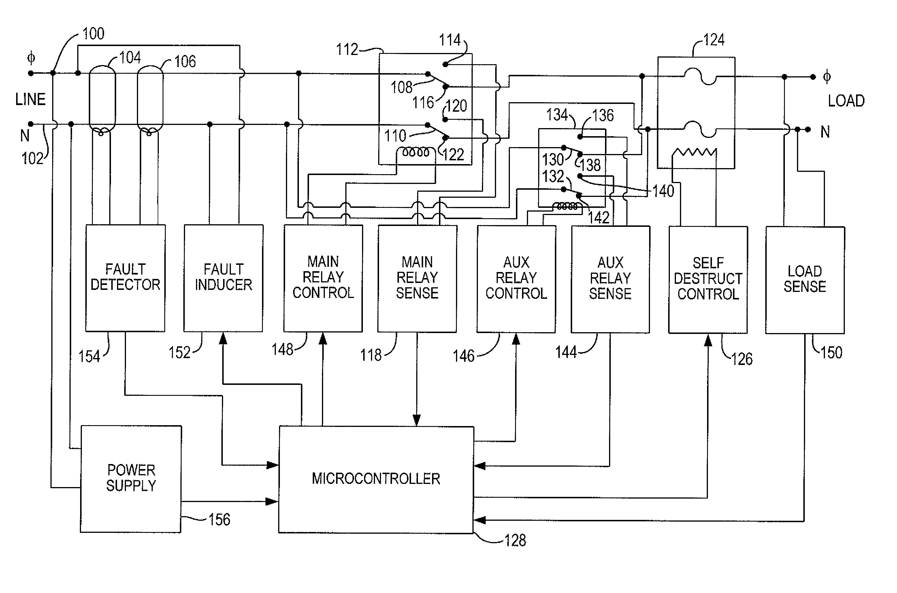
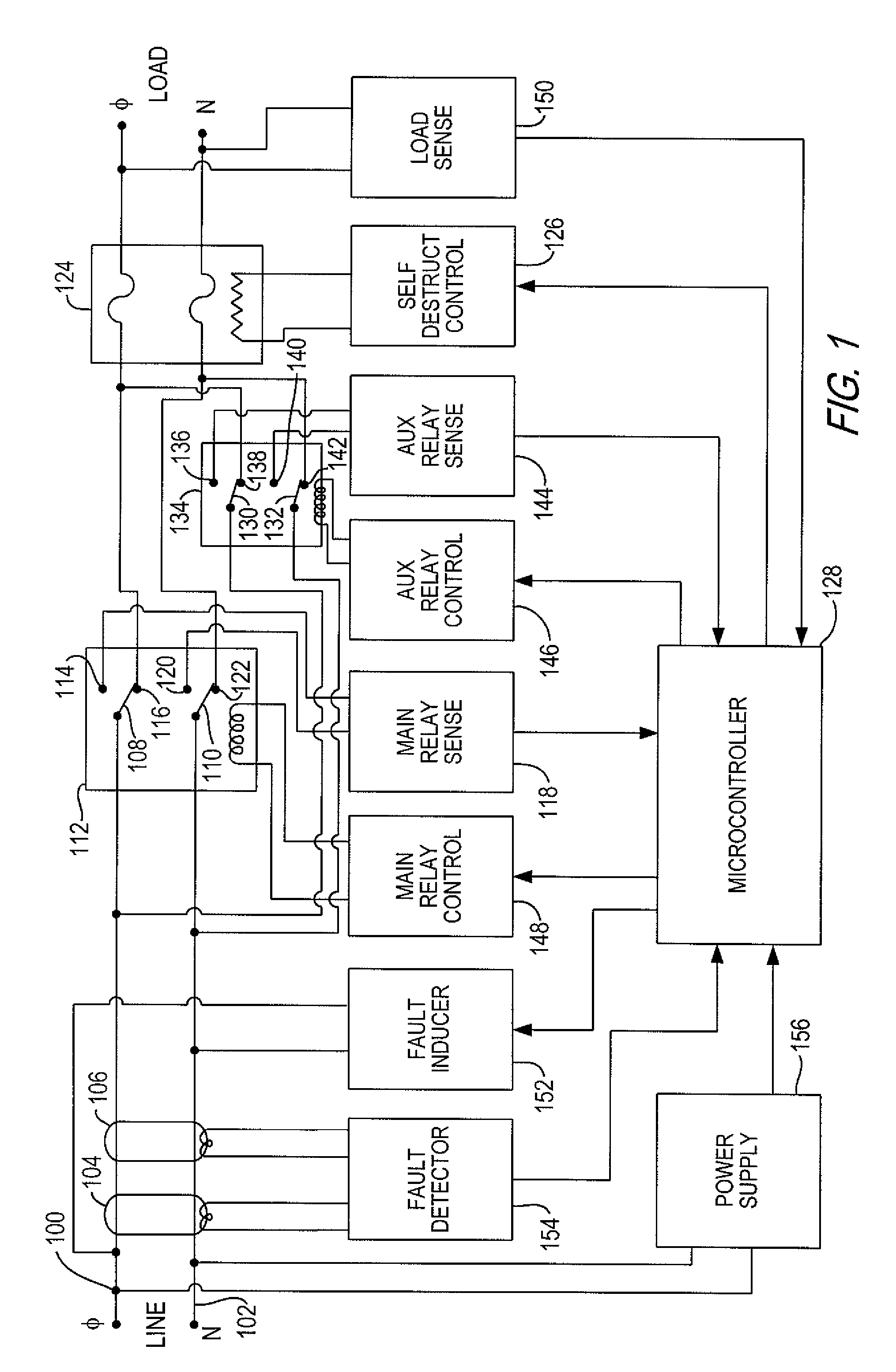
[0029] Referring to FIG. 1, there is shown a block diagram of a first embodiment of structure to obtain autonomous periodic automated self testing of a circuit interrupting device. Line phase 100 and neutral 102 conductors are coupled through differential transformer 104, 106 to movable contacts 108, 110 of main relay 112 which is a double pole double throw relay. Stationary contacts 114, 116, which cooperate with movable contact 108, are coupled to main relay sense circuit 118 and the load phase terminal respectively. Stationary contacts 120, 122, which cooperate with movable contact 110, are coupled to main relay sense circuit 118 and the load neutral terminal respectively. Heat sensitive elements such as fuses 124 can be connected in se...


PUM


Abstract

There is disclosed a self-testing circuit interrupting device which provides uninterrupted power to a load during a complete electronic and electromechanical components self test to allow autonomous periodic automated self testing without damaging or resetting connected load equipment.

Description

[0001] This application claims the benefit of U.S. Provisional Application No. 60 / 711,194 filed on Aug. 24, 2005.FIELD OF THE INVENTION [0002] The present invention is directed to the family of resettable circuit interrupting devices and systems which include, without limitation, ground fault circuit interrupters (GFCI's), arc fault circuit interrupters (AFCI's), immersion detection circuit interrupters (IDCI's), appliance leakage current interrupters (ALCI's), circuit breakers, contactors, latching relays and solenoid mechanisms. More particularly, the present application is directed to an autonomous periodic full function testing system for such devices and systems. DESCRIPTION OF THE RELATED ART [0003] The electrical wiring device industry has witnessed an increasing call for circuit breaking devices or systems which are designed to interrupt power to various loads, such as household appliances, consumer electrical products and branch circuits. In particular, electrical codes req...

Claims


Application Information

Patent Timeline
Patent Type & Authority Applications(United States)
IPC IPC(8): H02H3/16
CPCH02H3/335H01H2085/466
Inventor MERNYK, ROSSBRADLEY, ROGER M.
Owner LEVITON MFG
Learn More