Unicondylar knee implants and insertion methods therefor

Active Publication Date: 2008-01-17
HOWMEDICA OSTEONICS CORP
View PDF91 Cites 204 Cited by
  • Summary
  • Abstract
  • Description
  • Claims
  • Application Information

AI Technical Summary

Benefits of technology

[0016]The kit may also include a posterior resection guide having an upper end, a lower end having an elongated opening for receiving a cutting tool and a pin opening between the upper and lower ends. The pin opening of the posterior resection guide is desirably slidable over the alignment pin. The pin opening may include a first set of pin openings and a second set of pin openings that is closer to the upper end of the posterior resection guide than the first set

Problems solved by technology

In addition, access to damaged joints is limited and the necessity for reaching the areas to

Method used


Image

  • Unicondylar knee implants and insertion methods therefor
  • Unicondylar knee implants and insertion methods therefor
  • Unicondylar knee implants and insertion methods therefor

Examples


Embodiment Construction

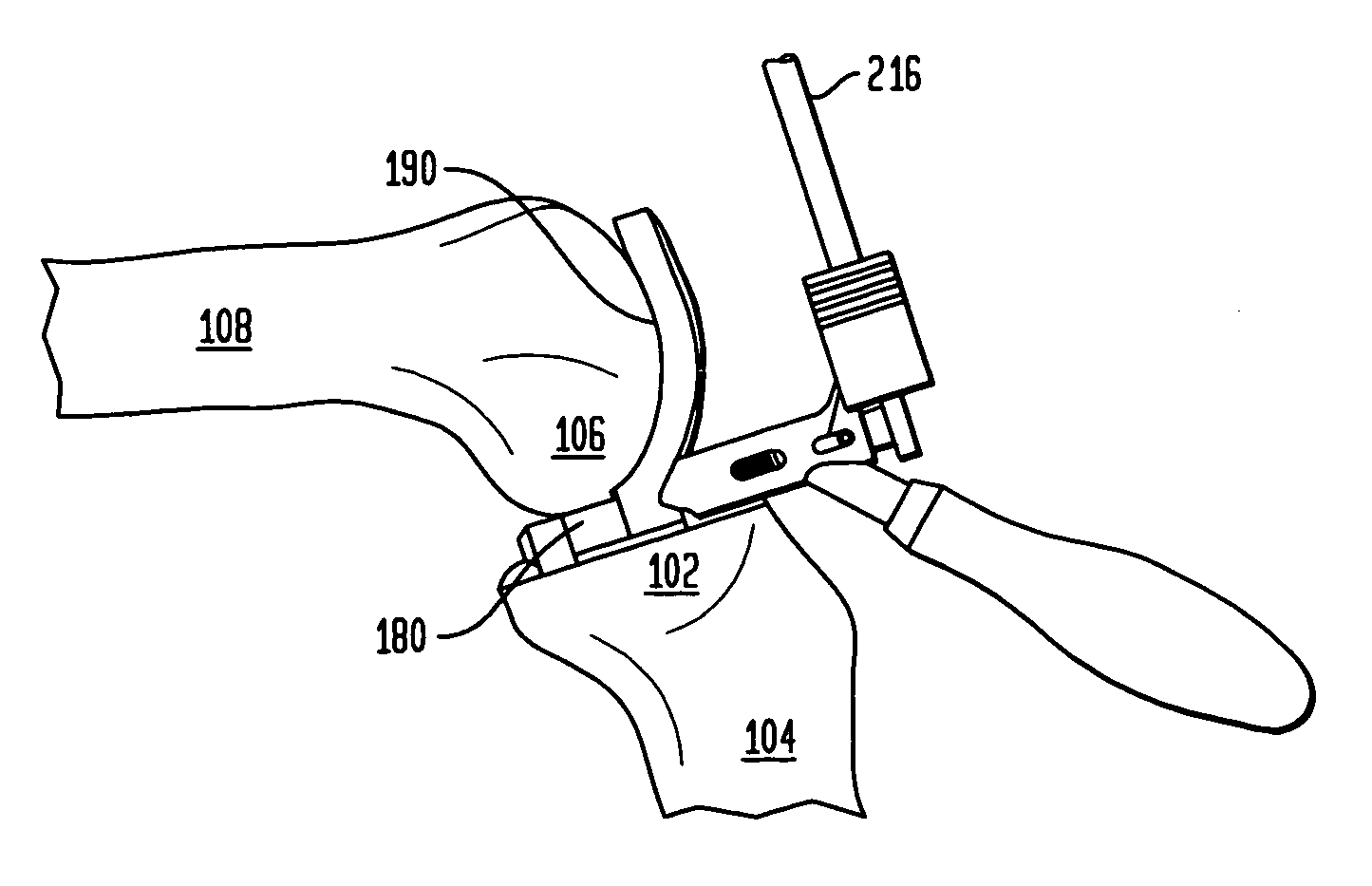
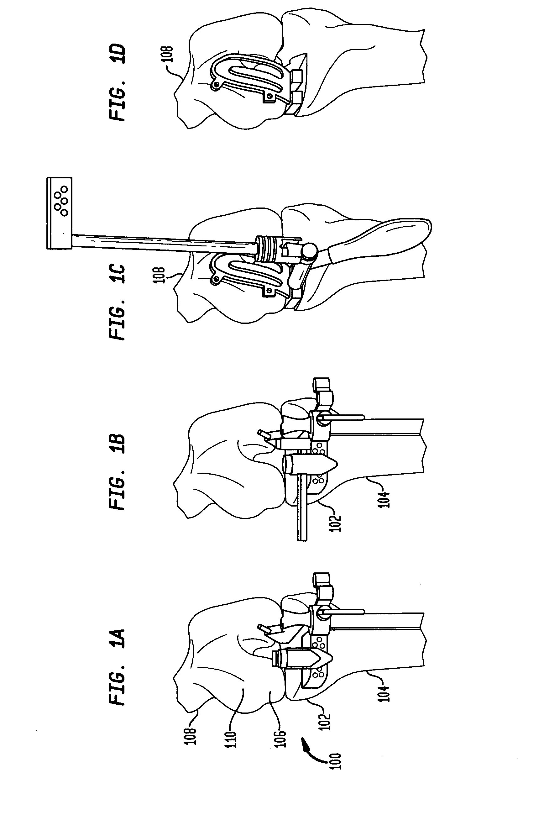
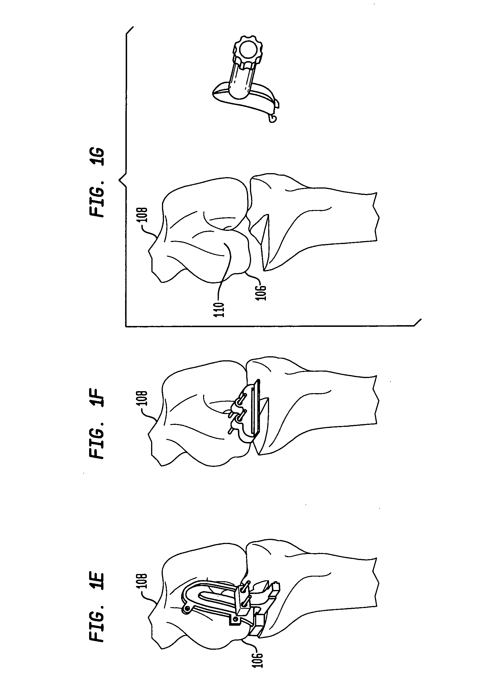
[0062]FIGS. 1A-1J show a method of preparing a knee for receiving an implant, in accordance with certain preferred embodiments of the present invention. In particular preferred embodiments, the method is used for preparing a knee to receive a knee implant such as a unicondylar knee implant. Referring to FIG. 1A, a knee joint 100 is located between a proximal end 102 of a tibia 104 and a distal end 106 of a femur 108. The distal end 106 of the femur 108 includes a distal condyle 110, which is the curved surface on a bone where it forms a joint with another bone. The femur 108 also has a posterior region of the femoral condyle.

[0063]In FIG. 1A, a tibial resection is performed on the proximal end 102 of the tibia 104. FIG. 1B shows a saggital resection being performed on the proximal end 102 of the tibia 104. FIG. 1C shows the positioning and alignment of a combination bur template and spacer block in a knee joint. The combination bur template and spacer block includes a spacer block t...


PUM


Abstract

A method of preparing a knee joint for receiving a unicondylar knee implant includes preparing a first seating surface at a proximal end of a tibia, and providing a combination bur template and spacer block, the bur template having an upper end, a lower end and a curved surface extending between the upper and lower ends thereof that is adapted to conform to a femoral condyle of a femur and the spacer block extending from the lower end of the bur template and having top and bottom surfaces. The method includes flexing the knee joint so that the prepared first seating surface at the proximal end of the tibia opposes a posterior region of the femoral condyle and inserting the combination bur template and spacer block into the knee joint so that the top surface of the spacer block engages the posterior region of the femoral condyle and the bottom surface of the spacer block engages the first seating surface at the proximal end of the tibia. While the spacer block is maintained between the femur and the tibia, the knee joint is extended until the curved surface of the bur template engages the femoral condyle of the femur. The bur template is anchored to the femur and used to guide burring of the femoral condyle for preparing a second seating surface on the femur. After burring the distal end of the femoral condyle, the posterior region of the femoral condyle is resected.

Description

BACKGROUND OF THE INVENTION[0001]The present invention generally relates to implants and more specifically relates to method and apparatus for preparing bone for receiving an implant.[0002]The use of prosthetic implants to replace damaged natural joints, or portions of such joints, in the body has become widespread as medical and technological advances have joined to provide improved materials and configurations for prosthetic implants and innovative procedures for implanting these devices. The basic objective of such devices and procedures is to provide a repaired joint of maximum effectiveness, with a minimal intrusion into the body. Component parts of these prosthetic implants are utilized to replace portions of a natural joint which have become damaged, either through injury or disease, and it is usually necessary to remove portions of the natural joint beyond merely the damaged portions in order to enable stable and secure fixation of the component parts to the natural bone. In...

Claims


Application Information

Patent Timeline
IPC IPC(8): A61B17/00
CPCA61B17/155A61B17/157A61F2002/3895A61F2/4684A61B17/1764
Inventor D'ALESSIO, JERRYCOLLAZO, CARLOS E.
Owner HOWMEDICA OSTEONICS CORP
Why Eureka
Try Eureka