
Seat
a seat and seat technology, applied in the field of seats, can solve the problems of muscle fatigue and insufficient support power of the seat, and achieve the effect of reducing muscular fatigu
- Summary
- Abstract
- Description
- Claims
- Application Information
AI Technical Summary
Benefits of technology
Problems solved by technology
Method used
Image

Examples
first embodiment
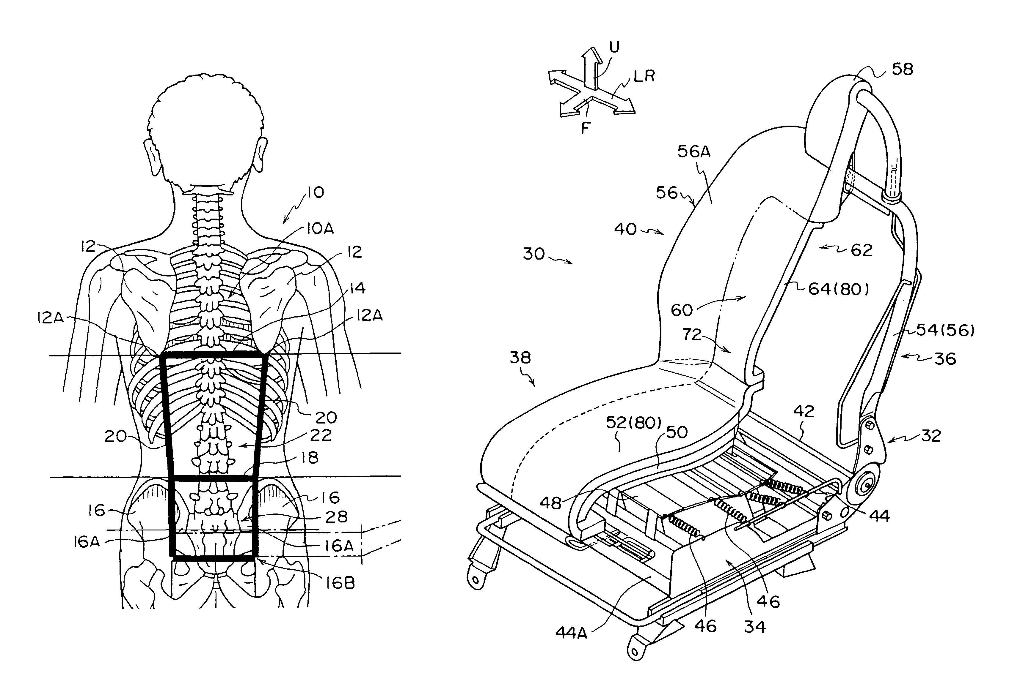
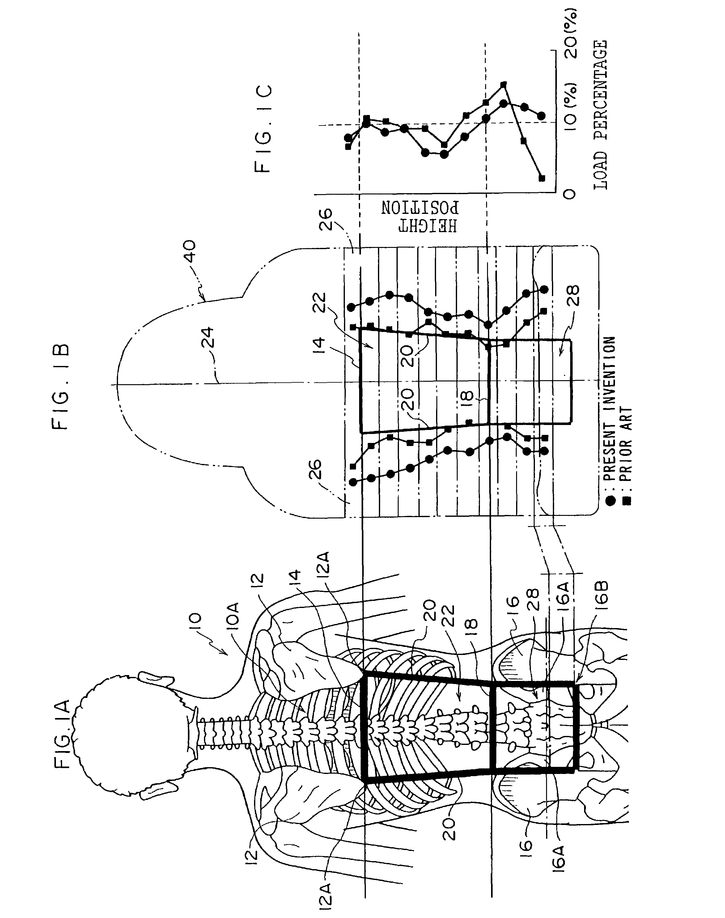
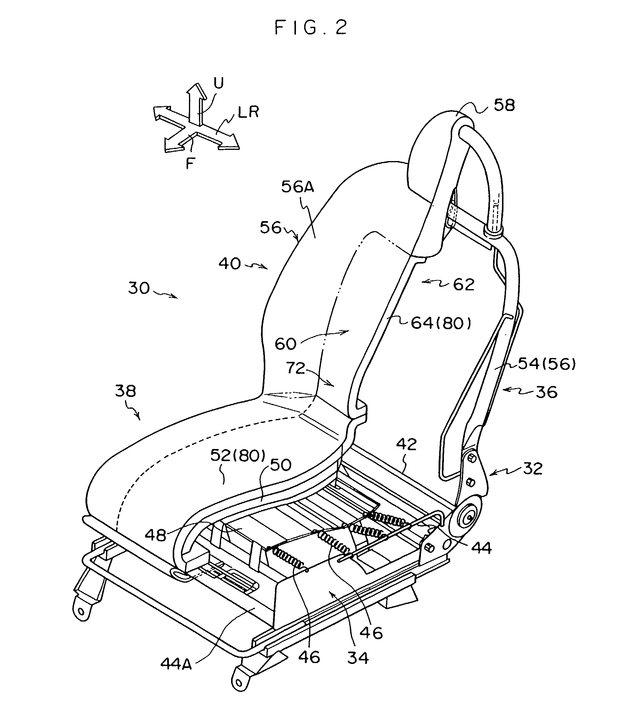
[0049]One embodiment of the present invention will be described in detail with reference to the accompanying drawings. FIG. 2A, FIG. 3A and FIG. 3B show a seat 30 for vehicles according to the present invention. Here in the following drawings: an arrow F designates a forward direction of the longitudinal direction of a vehicle; an arrow U designates an upward direction of the vertical direction; and arrows LR designate leftward and rightward directions.
[0050]As shown in FIG. 2, the seat 30 is provided with a seat frame 32. This seat frame 32 includes a seat portion frame 34 and a back portion frame 36. A seat cushion 38 is formed by mounting a cushion material for the seat portion on the seat portion frame 34, and a seat back 40 is formed by mounting a cushion material for the back portion on the back portion frame 36.
[0051]In the seat frame 32, the back portion frame 36 is rotatably connected on a support pin 42 arranged in the transverse directions to the seat portion frame 34, th...
second embodiment
[0107]FIG. 10A and FIG. 10B show a seat 100 according to the Here, this seat 100 is provided with a seat cushion 102, a seat back 104 and a head-rest portion 106.
[0108]In this seat 100, the seat cushion 102, the seat back 104 and the head-rest portion 106 are individually made of urethane and mounted on the seat frame 32 (although not shown). A predetermined surface material 108 is adhered to the individual surfaces of the seat cushion 102, the seat back 104 and the head-rest portion 106 as a general construction to provide a proper sense of elasticity and contact when they are seated.
[0109]This seat 100 is a so-called bucket type, in which side supporting portions 110 are formed on both the left and right sides of the seat back 104. A seat backrest portion 112 is formed between the side supporting portions 110.
[0110]In the seat 100, as shown in FIG. 10A, a slit 114 is formed in the seat backrest portion 112. This slit 114 is formed along the central line 24 and reaches the back si...
PUM
 Abstract
Description
Claims
Application Information