Headrest for head and neck

a head and neck technology, applied in the field of head and neck headrests, can solve the problems of cumbersome traditional pillows, large existing travel pillows, and often bulky, and achieve the effects of improving air flow to the neck, maximizing traveler's comfort, and increasing traveler's comfor

Active Publication Date: 2017-04-11
BULLBIRD LLC
View PDF69 Cites 24 Cited by
  • Summary
  • Abstract
  • Description
  • Claims
  • Application Information

AI Technical Summary

Benefits of technology

[0013]Certain embodiments have a housing comprising a material to maximize a traveler's comfort. Materials that are breathable, moisture wicking, soft, flexible, etc. are used in certain embodiments to increase a traveler's comfort when using certain embodiments of the present invention. In yet another embodiment, the present invention has an opening at a center region to improve air-flow to the neck. Certain embodiments have features that promote the comfort of a user. In certain embodiments, an apparatus can be heated and/or cooled for the comfort of a user. In certain embodiments, an apparatus includes a heating element, for example, a heating coil attached to a battery. In certain embodiments, a heating element, for example, heats a portion of an apparatus, such as a core piece, or a housing, as to provide comfort for a user. In certain embodiments, a heating element or a cooling element are integrated with an apparatus. Certain embodiments of an apparatus incorporate one or more magnets. It will be appreciated that magnets are incorporated in order to increase blood f

Problems solved by technology

Traditional pillows are often cumbersome during travel (e.g. during commercial airline travel, traditional pillows may be too large to fit in a carry-on luggage compromising space for other luggage).
Existing travel pillows are often bulky, taking up much of a traveler's limited carry-on luggage space or size allowance.
With limitations imposed on the size or number of items a person may carry, a traveler may have to make a decision whether or not to sacrifice personal comfort, because a bulky travel pillow occupies too much of the limited size allowance.
Certain travel pillows are volumetrically inefficient and occupies too much of the limited space in a luggage-piece.
However, many of the existing travel pillows do not properly fit within a head and neck region and do not provide support because of the improper fit.
Improper fit leads to lacking full support of the neck.
T

Method used


Image

  • Headrest for head and neck
  • Headrest for head and neck
  • Headrest for head and neck

Examples


Embodiment Construction

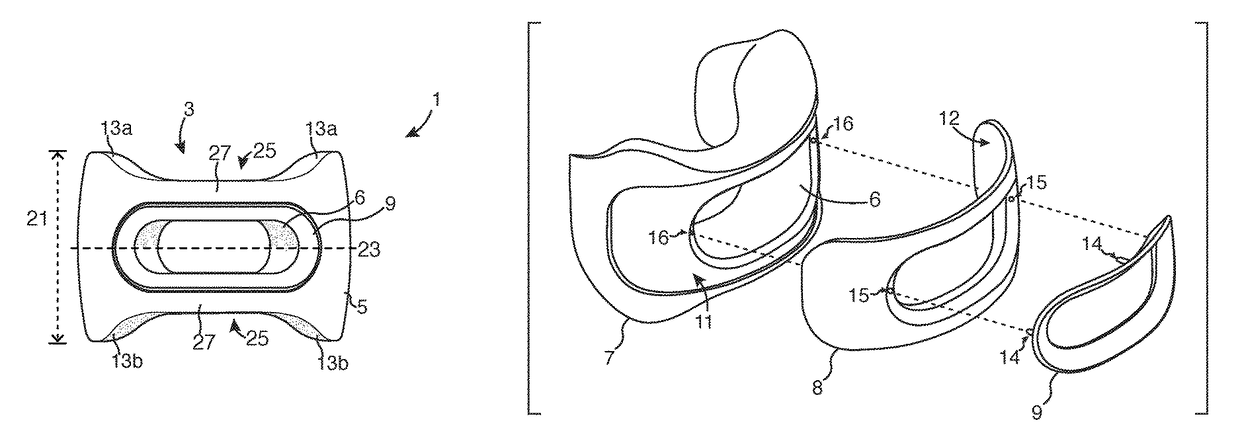
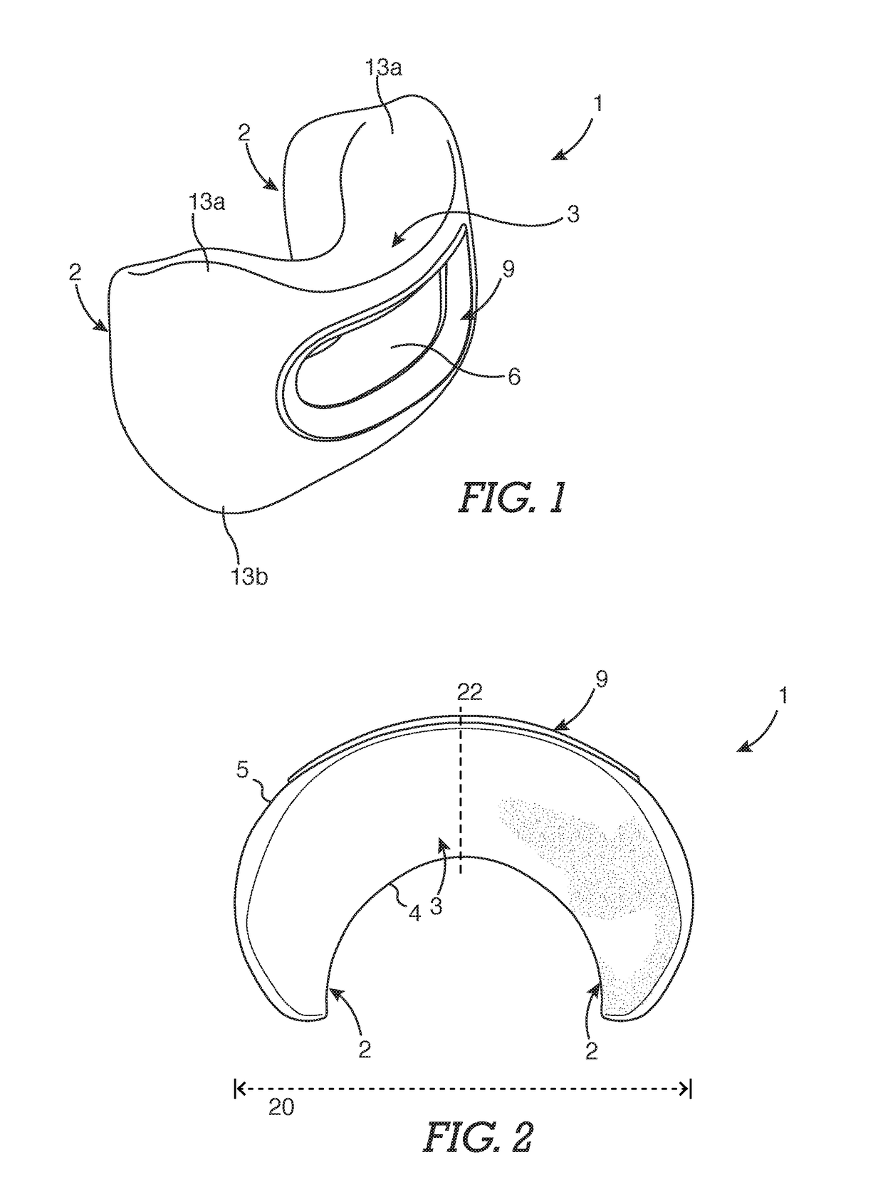
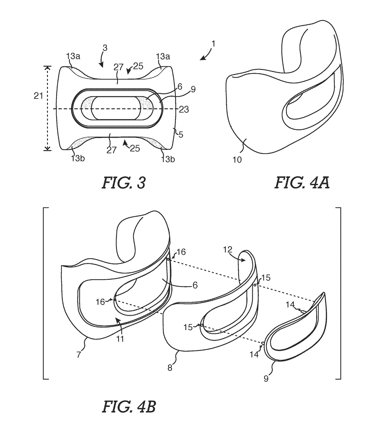
[0030]In certain embodiments, the supporting apparatus 1 is C-shaped, having a vertex or center region 3 and two end regions or lateral supports 2, as seen in FIG. 1 showing a perspective view, and FIG. 2 showing a top view. A center region 3 supports a user's nape, and two lateral supports 2 support a portion of a user's neck. An interiorly located inner wall 4 has a curved form fitting a user's neck. An exteriorly located outer wall 5 has a curved form. Referring to FIG. 1, and FIG. 3, certain embodiments of the invention comprise an opening 6. Referring to FIG. 5B showing a cross-sectional view of certain embodiments, such opening 6 spans from the outer wall 5 of a center region to the inner wall 4 of a center region. It will be appreciated that this opening or channel allows venting of air to facilitate airflow. An opening 6, also shown, for example, in FIG. 8A and FIG. 8B, allows adequate airflow to the user's neck to provide comfort to a user. Referring to FIG. 2, and FIG. 3, ...


PUM


Abstract

Certain embodiments of the present disclosure are related to a supportive apparatus for the head and neck. Embodiments of the invention incorporate a C-shaped apparatus shaped to support the posterior region of the neck. A center region found in certain embodiments of the C-shaped apparatus is placed on the posterior of a neck. Lateral supports found in certain embodiments of the C-shaped apparatus are placed on the lateral aspect of a neck. Embodiments of the invention include an opening across a center region functioning to support the apparatus, and to further act as to ventilate a user's nape.

Description

CROSS REFERENCE TO RELATED APPLICATIONS[0001]This application is a continuation of U.S. patent application Ser. No. 15 / 068,385, entitled “Headrest for Head and Neck” filed Mar. 11, 2016 currently pending. U.S. patent application Ser. No. 15 / 068,385 claims benefit to provisional patent application No. 62 / 300,406, entitled “Headrest for Head and Neck”, filed Feb. 26, 2016, the contents of each of which are incorporated by reference in their entirety for all purposes.FIELD OF THE INVENTION[0002]Embodiments of the present disclosure are related to headrests for the head and neck, and improvements thereof.BACKGROUND OF THE INVENTION[0003]There are over 300 million business travelers worldwide who fly several times a year. According to the United States Department of Transportation, since 2010, there are over 600 billion domestic airline passengers every year, and over 150 billion international airline passengers every year (Bureau of Transportation Statistics T-100 Market data, Passenger...

Claims


Application Information

Patent Timeline
IPC IPC(8): A47G9/10B60N2/48A47C7/38B60N2/56A61G7/10
CPCB60N2/48B60N2/5664A47G9/1081A47C7/383A61G7/1084B60N2/885B60N2/80
Inventor MADDOCKS, GLENNO'MEARA, SEAN
Owner BULLBIRD LLC
Why Eureka
Try Eureka