Foldable metal wall frame assemblies for use in residential and commercial structures

a technology of metal wall frame and prefabricated frame, which is applied in the direction of girders, walls, joists, etc., can solve the problems of existing roll forming technology, slow progress, and moderate increase, and achieve the effect of enhancing the transfer of structural loads and ensuring reliable load transfer

Inactive Publication Date: 2008-01-24
BH LEGACY
View PDF28 Cites 23 Cited by
  • Summary
  • Abstract
  • Description
  • Claims
  • Application Information

AI Technical Summary

Benefits of technology

[0016] Still another object of the present invention is to provide a pre-fabricated, foldable metal wall frame unit which is capable of easy transportation and selective erection on the site of residential or commercial building construction.
[0017] A further object of the invention is to provide a pre-fabricated, foldable metal wall frame unit which is adapted for ensuring good load transfer in load-bearing wall applications.
[0024] In still another modification, the track member center web includes a pair of raised transfer pads defining a depression cavity therebetween at the junction of the stud element end portions and the track member web to enhance the transfer of structural loads from the first track member to the second track member through the stud elements when the wall frame is in a fully unfolded and erect position.
[0025] An additional modification of the invention is in the form of a foldable wall frame having upper and lower track members. Each track member has a center web and a pair of opposite side flanges, the track members being spaced from each other with their respective side flanges projecting toward each other. A plurality of spaced stud elements are also provided with each having a center web, a pair of opposite side flanges and a pair ledge portions projecting inwardly from the edges of the flanges. Each stud element has first and second end portions and is arranged substantially parallel between the track members. A first attachment element pivotally secures the first end portion of each stud element to the upper track member. A second attachment element pivotally secures the second end portion of each stud element to the lower track member. The first and second pivotal attachment elements enable the upper track member to be folded down proximate the second track member for storage and transportation. Finally, a load transferring mechanism is disposed at the junctions of the first and second stud end portions and the upper and lower track members for enhancing and creating reliable load transference between the upper and lower track members when the wall frame is in a fully unfolded and erect position.

Problems solved by technology

Nonetheless, this progress has been a slow, moderate increase as opposed to the extreme dominance of steel framing vs. wood stick framing which has occurred in the commercial construction field.
Among the obstacles faced are entrenched traditional residential construction approaches as well as production methods for steel framing components.
Assuming that the roll tooling has been properly designed to avoid this particular problem, there are a number of other factors which still cause problems in existing roll forming technology.
While the formation of metal wall frame studs and tracks as well as the preassembly of wall frame sections from such studs and tracks has been enhanced by the inventions of the above-referenced patent application, there still exists a number of problems relating to the acceptance and use of metal wall frame structures in the residential building market.
One such problem involves teaching new assembly and construction techniques for on site formation of metal wall frames from the stud and track components to individuals who are used to using wood framing members.
While one approach to lessen this problem involves the preassembly of basic metal wall frame structures at a location remote to the residential construction site, this solution creates a yet another set of new problems including the costs and complexities of transporting, unloading and then connecting the large and cumbersome preassembled metal wall frame structures.

Method used


Image

  • Foldable metal wall frame assemblies for use in residential and commercial structures
  • Foldable metal wall frame assemblies for use in residential and commercial structures
  • Foldable metal wall frame assemblies for use in residential and commercial structures

Examples


Embodiment Construction

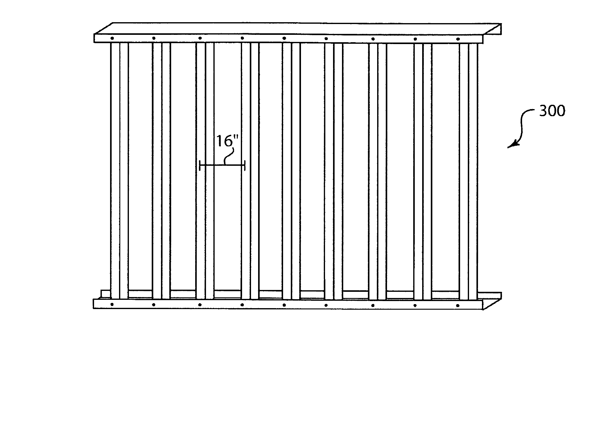
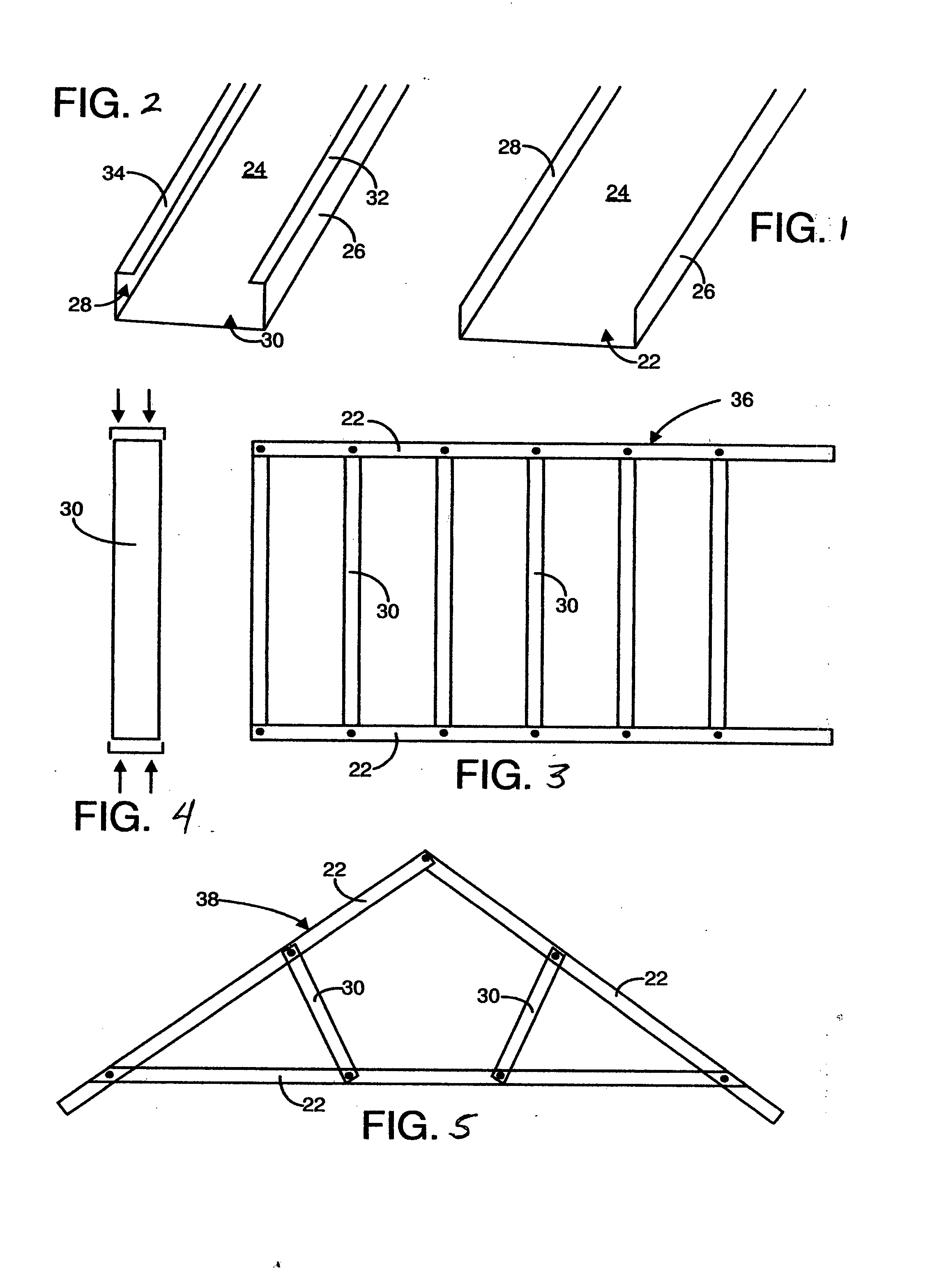
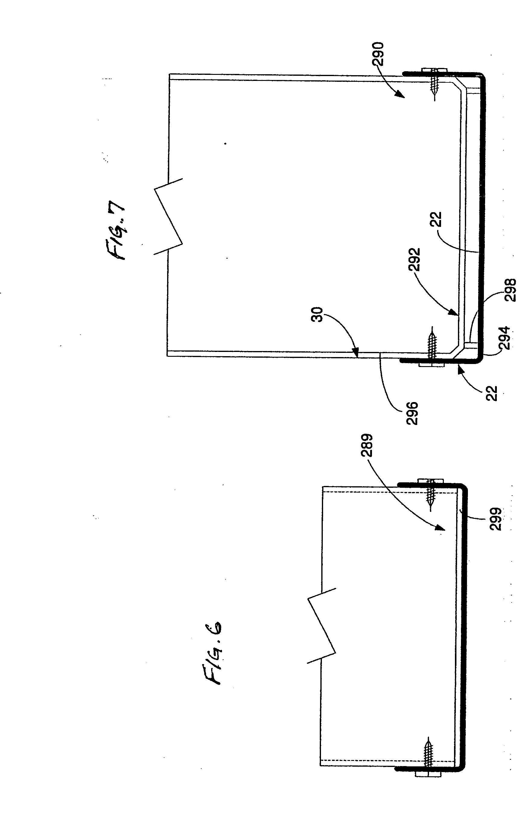
[0063] The present invention is a multifaceted foldable metal wall frame arrangement for residential and commercial building frames and the assembling of building structures therefrom. Referring first to FIGS. 1-5, metal sheets may be formed using any desired process into metal frame components, but preferably using the process and apparatus of the above-referenced related pending patent application. In the present invention, substantially U-shaped metal frame components are utilized and interconnected for use in residential and commercial building frame structures. One of the primary components formed using the present invention is a metal track member 22 having a center web portion 24 and a pair of upright flanges 26, 28 that are preferably angled at approximately 90° relative to the web portion 24. The other primary component in a metal wall frame is a stud element 30. The stud element 30 includes a center web portion 24 having upright flanges 26, 28 as in the track member 22. In...


PUM

PropertyMeasurementUnit
curvature radiusaaaaaaaaaa
relative movementaaaaaaaaaa
widthaaaaaaaaaa

Abstract

A foldable wall frame is disclosed and includes first and second track members spaced from each other, each track member having a center web and a pair of opposite side flanges. A plurality of spaced stud elements are positioned between and substantially perpendicular to the track members with each stud element having a first and a second end portion. A first attachment element is provided for pivotally securing the first end portion of each said stud element to the first track member. A second attachment element is also provided for pivotally securing the second end portion of each stud element to the second track member. The first and second pivotal attachment elements enable the first track member to be folded down proximate the second track member for storage and transportation, and to be unfolded at a construction site for installation into a building structure.

Description

CROSS REFERENCE TO RELATED APPLICATIONS [0001] This application is a continuation-in-part of co-pending U.S. patent application Ser. No. 11 / 446,317, filed Jun. 2, 2006, to William C. Heirich entitled, “Apparartus for the Fabrication of Metal Wall Frame Members and Assembly of Wall Frames Therefrom, and Foldable Wall Frame Structures”, the contents of which are hereby expressly incorporated herein by reference.BACKGROUND OF THE INVENTION [0002] 1. Field of the Invention [0003] The present invention relates generally to the fabrication and assembling of building frame components and, more particularly, to devices and structures relating to frame components and assemblies made of metal. Specifically, the present invention relates to prefabricated foldable metal wall frame members which enable easy transportation and on-site assembly of the same for both commercial and residential structures. [0004] 2. Description of the Prior Art [0005] In general, wall structures for both residential ...

Claims


Application Information

Patent Timeline
Patent Type & Authority Applications(United States)
IPC IPC(8): E04C3/04
CPCB21D5/08E04B2/7457E04B2/763E04C2003/0473E04B2001/2448E04C3/07E04B2/767
Inventor HEIRICH, WILLIAM C.
Owner BH LEGACY
Why Eureka
Try Eureka