
Wheel Support Device

a technology for supporting devices and wheels, which is applied in the direction of shock absorbers, electric propulsion mountings, transportation and packaging, etc., can solve the problems of wheel receiving unexpectedly large external force and and achieve the effect of suppressing the degradation of riding comfort of vehicles

Inactive Publication Date: 2008-01-24
TOYOTA JIDOSHA KK +1
View PDF10 Cites 31 Cited by
  • Summary
  • Abstract
  • Description
  • Claims
  • Application Information

AI Technical Summary

Benefits of technology

[0007] An object of the present invention is to provide a wheel support device that suppresses degradation in riding comfort of a vehicle.

Problems solved by technology

In the in-wheel motor driving system disclosed in the above document, however, the outer frame housing the motor is supported by the suspension, and thus, the wheel may receive unexpectedly large external force depending on the road conditions and the like.
If the outer frame comes into contact with the other components, sound and impact will be transmitted to the vehicle body, leading to degradation in riding comfort of the vehicle.

Method used


Image

  • Wheel Support Device
  • Wheel Support Device
  • Wheel Support Device

Examples


first embodiment

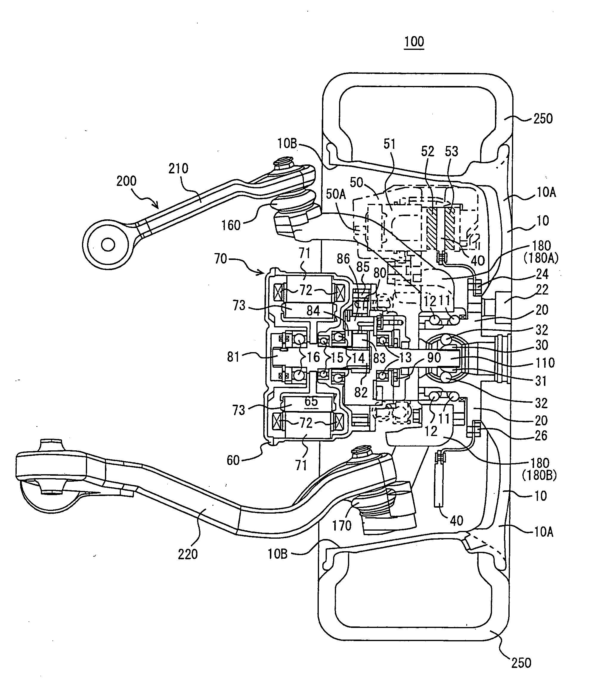
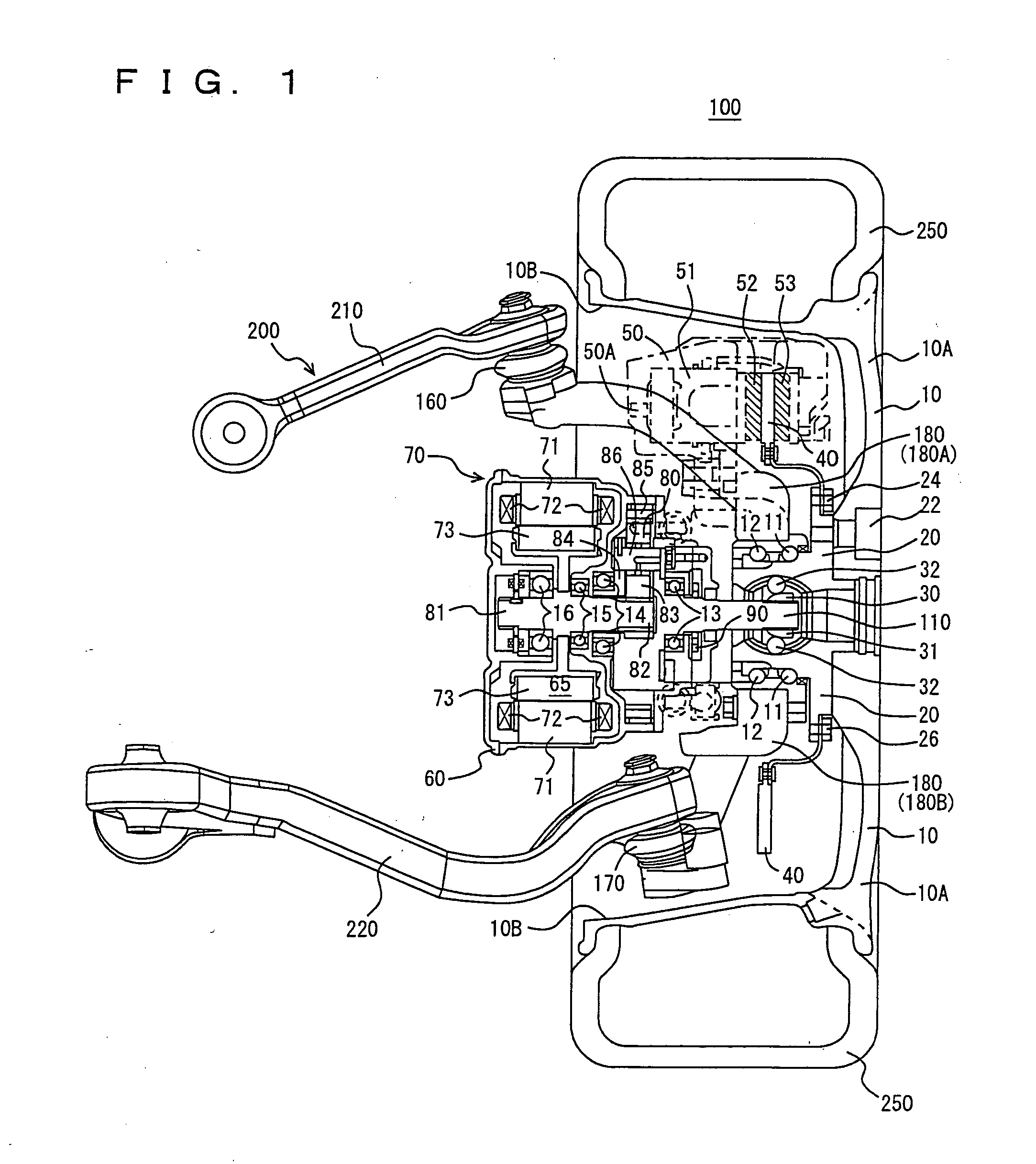
[0030] As shown in FIG. 1, a motor-driven wheel 100 supported by a wheel support device 200 according to a first embodiment of the present invention is formed with a wheel disk 10, a wheel hub 20, a constant velocity joint 30, a brake rotor 40, a brake caliper 50, an in-wheel motor 70, and a tire 250.

[0031] In-wheel motor 70 is formed with a case 60, a motor 65, a planetary gear 80, an oil pump 90, a shaft 110, and an oil passage (not shown).

[0032] Wheel support device 200 is formed with a dynamic mass damper mechanism (not shown), ball joints 160, 170, a knuckle 180, an upper arm 210, a lower arm220, and a shock absorber (not shown).

[0033] Wheel disk 10 has an approximately cup shape, and is formed with a disk portion 10A and a rim portion 10B. Wheel disk 10 may be configured to accommodate wheel hub 20, brake rotor 40, brake caliper 50, and in-wheel motor 70. Wheel disk 10 is coupled to wheel hub 20 by fastening disk portion 10A to wheel hub 20 by a bolt or a nut (not shown) at...

second embodiment

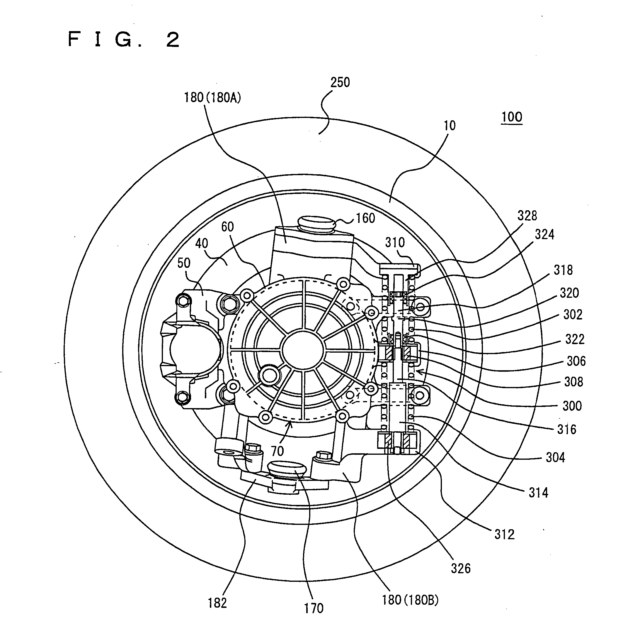
[0065] A wheel support device according to a second embodiment of the present invention will now be described. Compared to the configuration of wheel support device 200 according to the first embodiment described above, the wheel support device according to the present embodiment differs in the configuration of absorber 314 and also differs in that it includes cushioning members 332 and 334 instead of cushioning members 322 and 324. Otherwise, the configuration is identical to that of wheel support device 200 according to the first embodiment described above. They are denoted by the same reference characters, and their functions are identical. Thus, detailed description thereof will not be repeated here.

[0066] The wheel support device 200 according to the present invention is characterized in that it includes a case 60 that vibrates together with the vibration of in-wheel motor 70, a knuckle 180 that restricts the vibration of the motor by coming into contact with case 60 at a pres...


PUM


Abstract

A wheel support device (200) includes a spring (302, 304) fitted to an in-wheel motor (70) and damping the vibration of a motor-driven wheel (100) and the in-wheel motor (70) by extending and retracting, a knuckle (180) attached to the spring (302, 304) and rotatably supporting the motor-driven wheel (100), a center part (306) of a dynamic mass damper mechanism (300) vibrating together with the in-wheel motor (70) by a force given from a road surface when a vehicle runs, an upper part (310) thereof restricting the vibration of the in-wheel motor (70) by coming into contact with the center part (306) at a prescribed region, and a cushioning member (322, 324) fitted to a portion of the center part (306) or the upper part (310) corresponding to the prescribed region brought into contact with the other.

Description

TECHNICAL FIELD [0001] The present invention relates to a wheel support device, and particularly to a wheel support device suppressing degradation in riding comfort of a vehicle. BACKGROUND ART [0002] In a conventional in-wheel motor driving system, a motor is disposed in an outer frame, and an output shaft of the motor is rotatably supported by the outer frame via a bearing. The output shaft has one end coupled to a wheel via a planetary gear. [0003] Further, the outer frame housing the motor is coupled to a suspension arm via a ball joint. The suspension arm is coupled to the vehicle body via a shock absorber. [0004] As such, in the conventional in-wheel motor driving system, the outer frame housing the motor is coupled to the vehicle body via the ball joint and the suspension arm. [0005] As a conventional in-wheel motor driving system, one having a hollow motor supported by a motor suspension is known from Go Nagaya, Yasumichi Wakao, Akihiko Abe, “Development of an In-Wheel Motor...

Claims


Application Information

Patent Timeline
IPC IPC(8): F16F9/512B60G13/16B60B35/14B60K7/00F16F15/02
CPCB60G3/20B60G13/16B60G2202/12B60G2204/30B60K2007/0092B60K7/0007B60K17/046B60K2007/0038B60G2300/50
Inventor MIZUTANI, RYOJIKURATA, FUMITOSUZUKI, SHUUETSUSAKURAI, JUNICHIRO
Owner TOYOTA JIDOSHA KK
Features
  • Generate Ideas
  • Intellectual Property
  • Life Sciences
  • Materials
  • Tech Scout
  • Unparalleled Data Quality
  • Higher Quality Content
  • 60% Fewer Hallucinations
Learn More