
Image forming apparatus including belt traveling unit which detects drifiting of belt postion

a technology of image forming apparatus and traveling unit, which is applied in the direction of electrographic process apparatus, instruments, optics, etc., can solve the problems of correction mechanism misdetecting the position of the transfer belt, the quality of the image to deteriorate, and the belt to dri

Inactive Publication Date: 2008-01-24
RICOH KK
View PDF5 Cites 7 Cited by
  • Summary
  • Abstract
  • Description
  • Claims
  • Application Information

AI Technical Summary

Benefits of technology

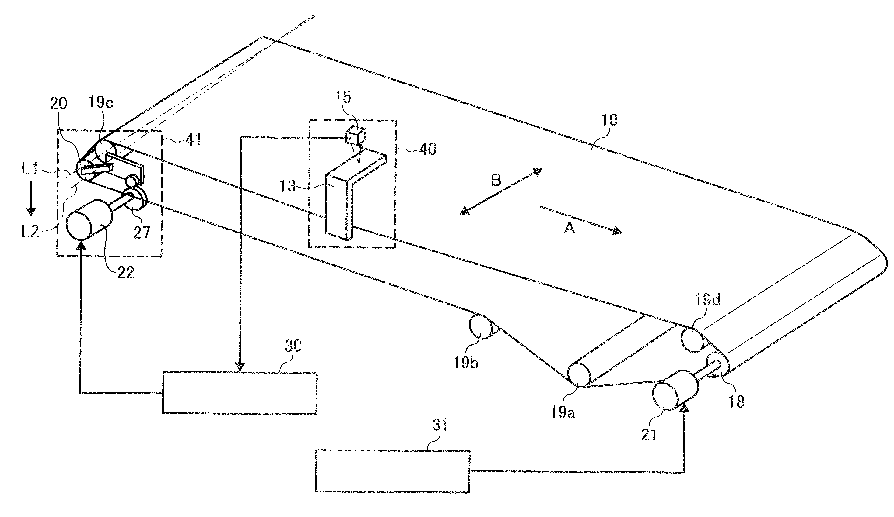
[0043]The correction unit may adjust a tilt angle of the correction roller to correct drifting of the belt in the width direction thereof.

Problems solved by technology

When using a belt, in a case where the tension balance is changed in a belt width direction, there may be such a problem that the belt may drift toward a roller around which the belt is wound or toward a shaft direction of a pulley.
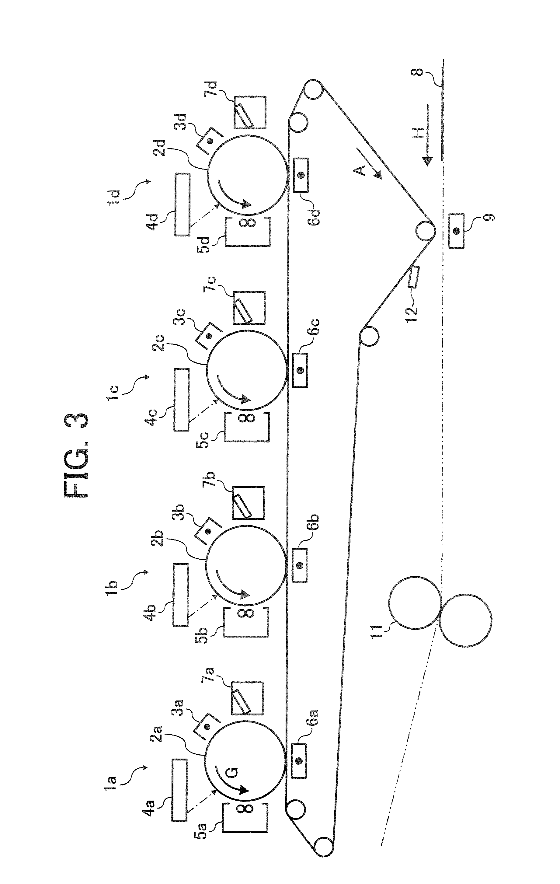
When the belt is utilized as a transfer belt on which the toner image is directly transferred from the photoreceptor drum, instead of a belt used as a sheet conveyance purpose, when belt drift occurs, the positional misalignment or color misalignment of toner images of different colors may occur, thereby causing the quality of an image to deteriorate.
The technical difficulty of the drift correction may be to accurately detect the position of the edge of the transfer belt in the width direction without misdetection.
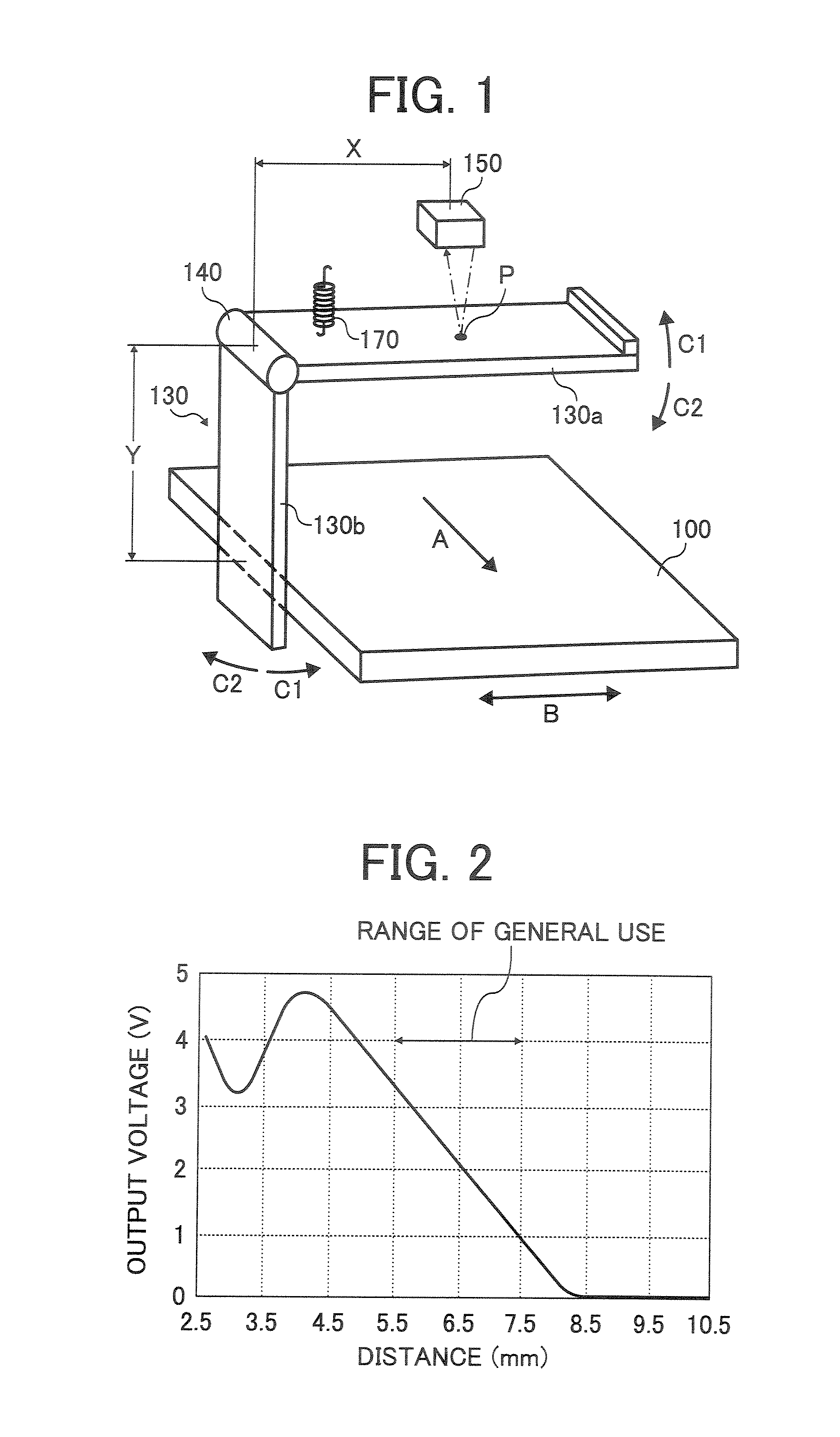
However, when using the drift detector with the detection range of 5.5 mm to detect the belt position located outside the range of the general use of the detection sensor, for example, the range less than 5.5 mm, the drift correction mechanism may misdetect the position of the transfer belt.
Furthermore, there may be a possibility that the transfer belt is damaged.
Thus, the above method may not be desirable.
However, when two drift detectors are used to detect the position of the transfer belt in the width direction, the cost may increase.
In addition, when detecting the belt position at the range less than 5.5 mm of the general use of the drift detector, there is a possibility that the detectors may misdetect the belt position due to characteristics of the drift detector.

Method used


Image

  • Image forming apparatus including belt traveling unit which detects drifiting of belt postion
  • Image forming apparatus including belt traveling unit which detects drifiting of belt postion
  • Image forming apparatus including belt traveling unit which detects drifiting of belt postion

Examples


Embodiment Construction

[0060]It will be understood that if an element or layer is referred to as being “on,““against,”“connected to” or “coupled to” another element or layer, then it can be directly on, against connected or coupled to the other element or layer, or intervening elements or layers may be present.

[0061]In contrast, if an element is referred to as being “directly on”, “directly connected to” or “directly coupled to” another element or layer, then there are no intervening elements or layers present. Like numbers refer to like elements throughout.

[0062]As used herein, the term “and / or” includes any and all combinations of one or more of the associated listed items.

[0063]Spatially relative terms, such as “beneath”, “below”, “lower”, “above”, “upper” and the like, may be used herein for ease of description to describe one element or feature's relationship to another element(s) or feature(s) as illustrated in the figures.

[0064]It will be understood that the spatially relative terms are intended to...


PUM


Abstract

A belt traveling unit includes an endless belt, a drive roller and a correction roller, a driving unit, a correction unit, a contact member, a position detector and a regulating member. The endless belt is spanned between a plurality of rollers. The driving unit rotates the drive roller to drive the belt. The correction unit adjusts a tilt angle of the correction roller to correct drifting of the belt in the width direction thereof. The contact member is rotatable in conjunction with traveling of the belt in the width direction thereof. The position detector detects a position of the contact member to detect a position of the belt in the width direction thereof. The regulating member is located at a position where the position detector does not misdetect the position of the belt when the contact member rotates.

Description

CROSS REFERENCE TO RELATED APPLICATIONS[0001]This patent application is based on and claims priority under 35 U.S.C. §119 to Japanese patent application No. JP2006-200262 filed on Jul. 24, 2006 in the Japan Patent Office, the entire contents of which are incorporated herein by reference.BACKGROUND OF THE INVENTION[0002]1. Field of the Invention[0003]The invention relates to a belt traveling unit, an image forming apparatus using the same, to a belt traveling unit which detects a position of a belt, an image forming apparatus including the same, and a method of forming an image.[0004]2. Discussion of the Background[0005]An image forming apparatus which forms not only a single color image, but also a multiple color image has been commonly used.[0006]An image forming apparatus capable of forming a multiple color image includes a tandem-type color image forming apparatus.[0007]The tandem-type color image forming apparatus may be equipped with a plurality of photoreceptor drums arranged ...

Claims


Application Information

Patent Timeline
Patent Type & Authority Applications(United States)
IPC IPC(8): G03G15/00
CPCG03G15/0131G03G2215/0158G03G2215/0119G03G2215/00156
Inventor RYO, TAKEMASATAO, SATORUTOMITA, SHINYA
Owner RICOH KK
Learn More