
Photon counting detector

a detector and photon technology, applied in the field of photon counting detectors, can solve the problems of significant trade-offs in complexity and/or effectiveness of corrective measures, and achieve the effects of high stability performance, high absorption material, and high absorption

Active Publication Date: 2021-09-30
KONINKLJIJKE PHILIPS NV
View PDF0 Cites 0 Cited by
  • Summary
  • Abstract
  • Description
  • Claims
  • Application Information

AI Technical Summary

Benefits of technology

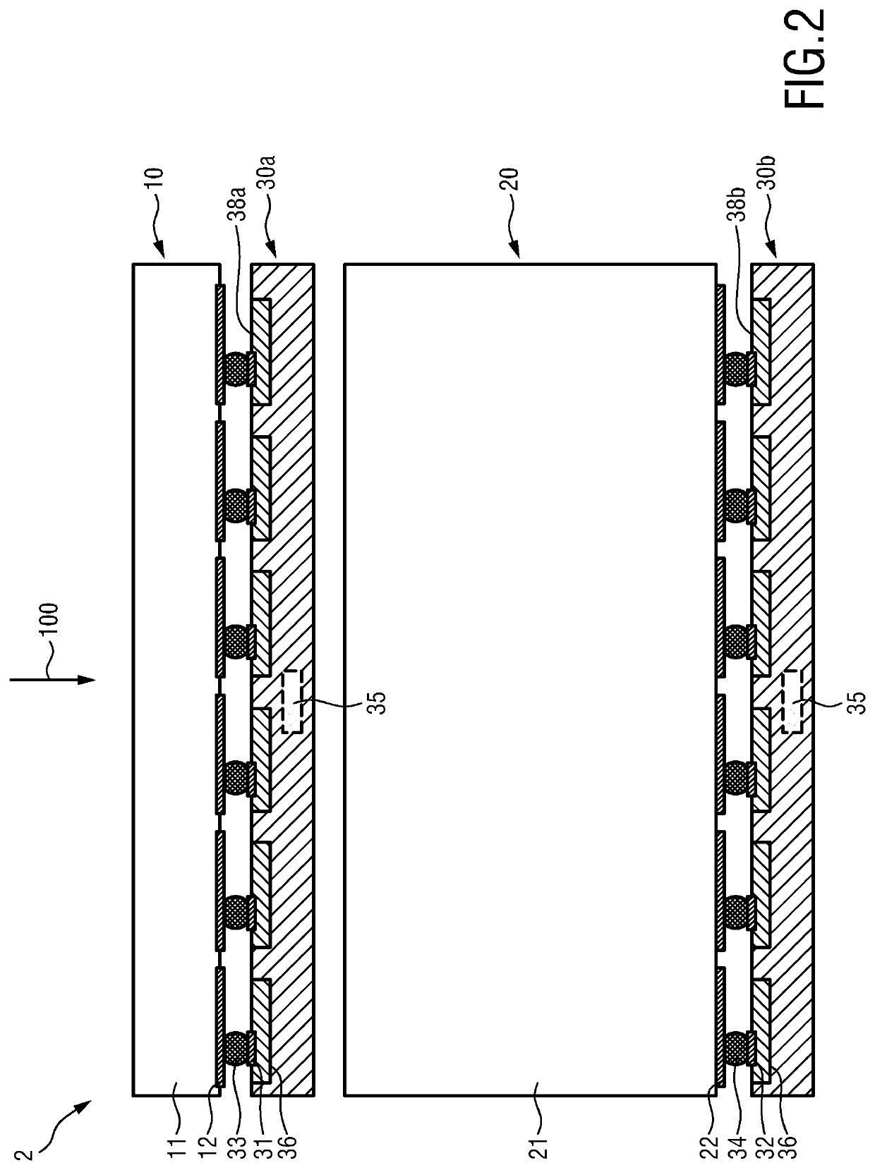
The patent describes a photon counting detector with two layers that absorb light in different ways. The first layer has low absorption and is made of GaAs or Si, which is stable but not suitable for CT as a standalone detector due to its low absorption. The second layer has high absorption and is made of Cd(Zn)Te or CdTe, which is unstable but provides sufficient absorption for CT. The detector uses a single ASIC substrate to carry both layers and processing circuitry to correct errors caused by the unstable second layer. The processing circuitry uses the first count signal to estimate the impinging electromagnetic radiation and correct the second count signal for errors caused by drift or changes in the signal part below the lowest energy threshold. The technical effect of this patent is to improve the accuracy of measurements and the final count signal by compensating for errors caused by the unstable second layer.

Problems solved by technology

A number of methods are known, however with significant trade-offs in complexity and / or effectiveness of the corrective measures.

Method used


Image

  • Photon counting detector
  • Photon counting detector
  • Photon counting detector

Examples


Embodiment Construction

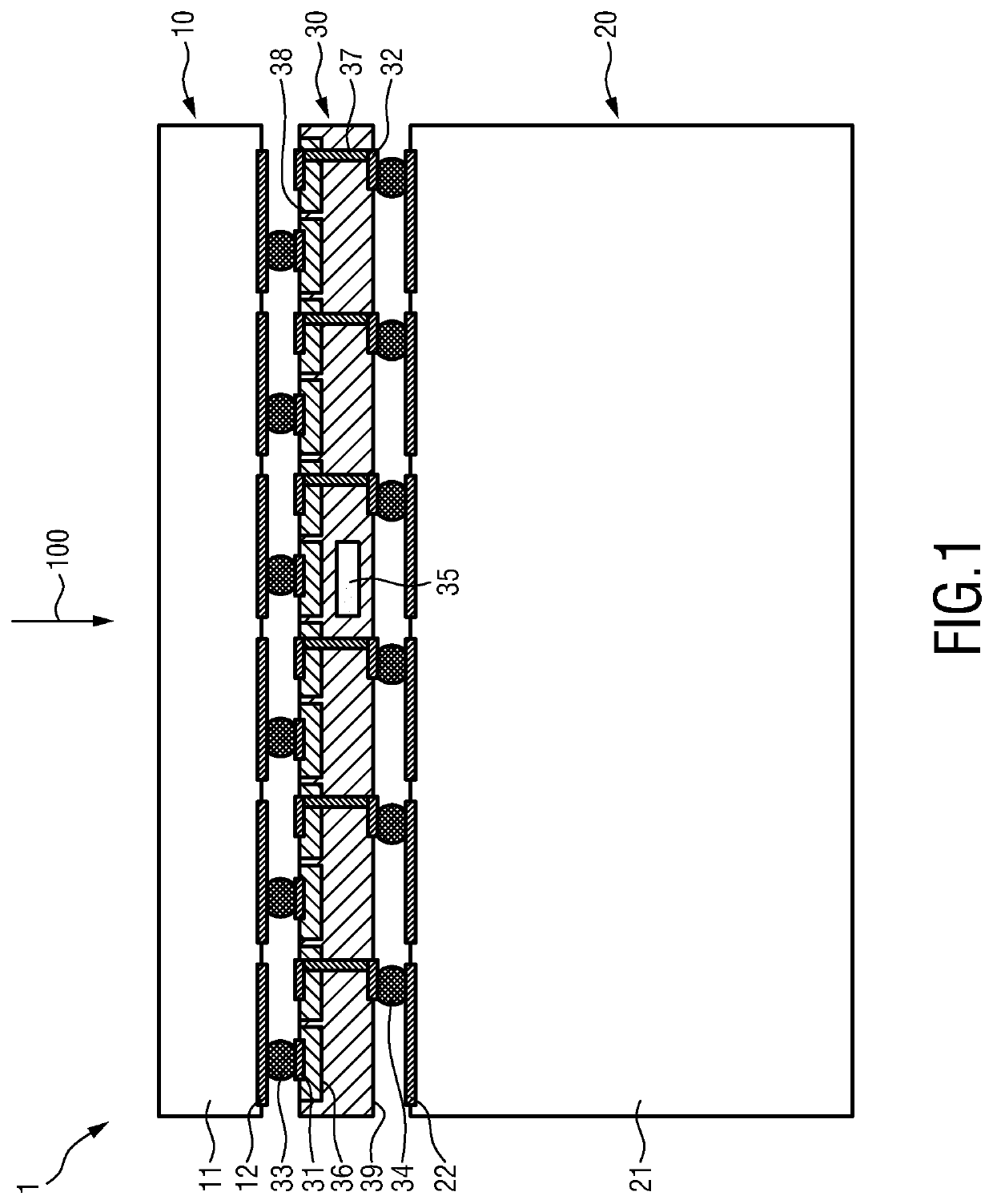
[0041]FIG. 1 shows a schematic diagram of a first embodiment of a photon counting detector 1. It comprises a first direct conversion layer 10, a second direct conversion layer 20 and a carrier layer 30.

[0042]The first direct conversion layer 10 comprises a low-absorption direct conversion material 11 for converting impinging high-energy electromagnetic radiation 100 (in particular x-ray radiation) into a first count signal and first electrical contacts 12. The low-absorption material may e.g. be GaAs. Good detection-grade GaAs sensors are available in e.g. 200 μm thickness (up to 500 μm). A 200 μm thick GaAs only absorbs about 24% of the impinging photons for a 120 kVp spectrum.

[0043]The second direct conversion layer 20 comprises a high-absorption direct conversion material 21 for converting impinging high-energy electromagnetic radiation 100 into a second count signal and second electrical contacts 22. The high-absorption direct conversion material 21 has a higher absorption than ...


PUM


Abstract

The present invention relates to a photon counting detector comprising a first direct conversion layer (10) comprising a low-absorption direct conversion material (11) for converting impinging high-energy electromagnetic radiation (100) into a first count signal and first electrical contacts (12), a second direct conversion layer (20) comprising a high-absorption direct conversion material (21) for converting impinging high-energy electromagnetic radiation (100) into a second count signal and second electrical contacts (22), said high-absorption direct conversion material having a higher absorption than said low-absorption direct conversion material, and a carrier layer (30, 30a, 30b) comprising first and second terminals (31, 32) in contact with the first and second electrical contacts and processing circuitry (35) configured to correct, based on the first count signal, the second count signal for errors, wherein said first direct conversion layer and the second direct conversion layer are arranged such that the high-energy electromagnetic radiation transmits the first direct conversion layer before it hits the second direct conversion layer.

Description

FIELD OF THE INVENTION[0001]The present invention relates to a photon counting detector and a correction device and method for a photon counting detector. The present invention relates further to a photon counting detection arrangement.BACKGROUND OF THE INVENTION[0002]The advent of energy-resolving photon counting spectral CT heavily relies on the maturity and stability of the direct conversion material. While further improvements on the material stability are forthcoming only slowly, methods to compensate the deviation from the expected number of counts need to be put in place. A number of methods are known, however with significant trade-offs in complexity and / or effectiveness of the corrective measures.[0003]US 2008 / 230709 A1 discloses a diagnostic imaging system including a high frequency electromagnetic energy source that emits a beam of high frequency electromagnetic energy toward an object to be imaged. An energy discriminating (ED) detector receives high frequency electromag...

Claims


Application Information

Patent Timeline
IPC IPC(8): G01T1/24G01T1/29
CPCG01T1/242G01T1/2928
Inventor STEADMAN BOOKER, ROGERROESSL, EWALD
Owner KONINKLJIJKE PHILIPS NV
Learn More