
Extracorporeal blood treatment machine comprising leakage detection and method of detecting leakages in dialysis fluid systems

a dialysis fluid system and extracorporeal technology, applied in the field of extracorporeal blood treatment machines, can solve the problems of reducing the duration of therapy, and reducing the number of false alarms advantageously. , the reliability of the system and the method, respectively, can be improved, and the effect of reducing the pollution of the inlet and/or outlet air apertur

Active Publication Date: 2017-10-31
B BRAUN AVITUM
View PDF4 Cites 1 Cited by
  • Summary
  • Abstract
  • Description
  • Claims
  • Application Information

AI Technical Summary

Benefits of technology

[0007]Based on the afore-described state of the art, it is an object underlying the present invention to eliminate the afore-stated drawbacks, especially to provide a possibility of leakage detection in the dialysis fluid system of an extracorporeal blood treatment machine, preferably a dialysis machine, which works comparatively safely, accurately and reliably in the case of small leakage quantities, by which continuous monitoring of the system in terms of leakage is possible, especially also during a current treatment substantially without disturbance thereof, which causes or requires no substantial extension or interruption of the treatment and is comparatively inexpensive.
[0014]In a preferred embodiment of the invention the at least one venting means includes a blower or is formed by the same. Such blower can be provided anyway under certain circumstances in the dialysis machine and preferably can serve for a parallel or simultaneous cooling of the machine. Especially advantageously, the housing can be vented by the venting means, i.e. air can be conveyed out of the housing by the venting means, preferably into the environment. In the housing a vacuum is formed vis-à-vis the environment so that the probability of inadvertent air leak except via the ventilation means or the outlet air aperture can be reduced by which air leak detection of humidity introduced into the air inside the housing due to leakage could be falsified or prevented.
[0018]In order to be able to safely detect even small leakages that cannot be detected in the case of a volume or mass flow ensuring sufficient cooling of the machine (i.e. a volume / mass flow which is relatively high), as the increase in humidity of the air quantity flowing through the housing would be too small for being detected, a measuring cycle can be interspersed in which the airflow guided through the housing can be set to be very small (smaller than the value set as a standard) or as small as possible. During such measuring cycle sufficient cooling of the machine might no longer be completely provided, however in this way also small leakages can be safely detected, as due to the small volume / mass flow and the low flow rate, respectively, they cause an increase in humidity of the airflow guided through the housing in the case of leakage which is sufficient or distinct for being detected.
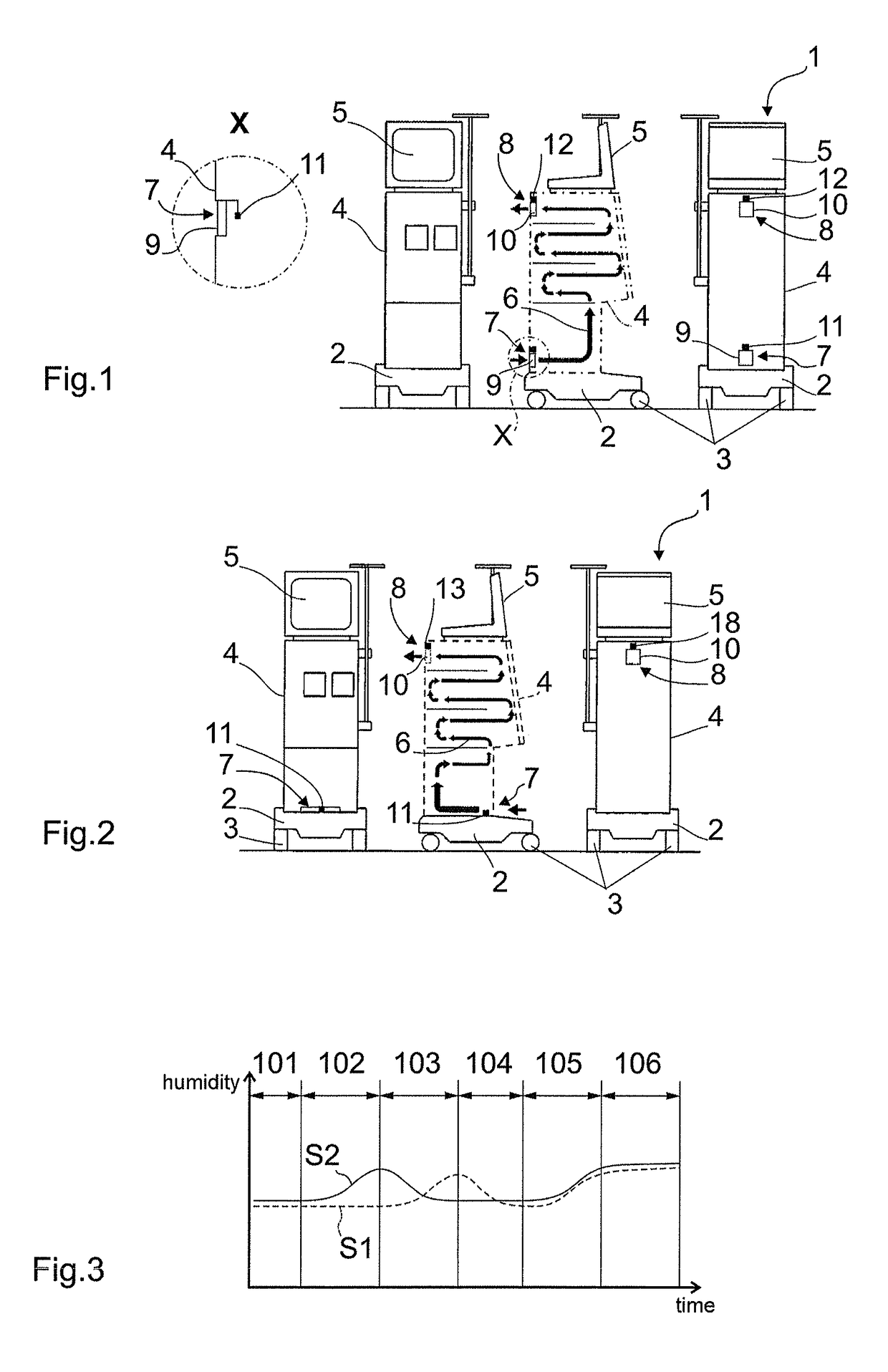
[0019]In order to be able to detect minimal leakages in an embodiment of the invention the airflow through the housing is stopped for a particular period of time, especially prior to a measuring cycle, e.g. by completely down-regulating the venting means. During this period of time in which no air is flowing through the housing, even in the case of minimal leakages an increase (enrichment) in humidity of the air quantity present in the housing occurs, which can be easily and safely determined during subsequent measurement. In total, the invention advantageously allows detecting leakages almost independently of the quantity and / or the mass or volume flow of the escaping dialysis fluid over a wide range of mass and volume flows. It is possible to reliably and quickly detect leakages of different magnitude, even small and minimal leakages. Cooling of the machine can be operated without any substantial impairment.
[0022]In an advantageous embodiment of the method of the invention the system can be calibrated, especially before the start of treatment. It can be checked whether fluid is provided inside the housing of the dialysis machine. In this case after a first ventilation cycle of the housing the direction of the flow through the housing is reversed. In the event that inside the housing no fluid is provided, an offset of the sensor used for detecting parameters of the inflowing or outflowing air quantity is equal in the normal direction of flow and in the reversed direction of flow through the housing. If fluid, especially dialysis fluid, has escaped from the dialysate system due to a leak and is present in the interior of the housing, the two offset values measured during calibration are different. The sensor at the respective outlet air aperture indicates the higher value. When the offset remains constant in both directions of flow through the housing, it can be compensated by calibrating the sensor. Of particular advantage, such checking or calibration by reversing the direction of flow of the air through the housing can also be carried out during a treatment without impairing the latter.
[0023]According to an embodiment of the invention, the direction of flow through the housing is repeatedly alternated, especially regularly alternated. This can be done in parallel to the usual treatment operation. In this way, a drift of the sensor / sensors can be detected more or less promptly and can be corrected, if desired. Moreover, pollution of the inlet and / or outlet air aperture can be reduced by repeated reversal of the direction of flow through the housing. Finally a plausibility check can be performed by reversing the direction of flow through the housing 4 after additional humidity has been determined in the housing. In this way it can be determined whether an increase in the measuring value was in fact caused by dialysis fluid entered from the dialysis fluid system into the housing or else is based only on a measuring error or on increasing air humidity of the ambient air. Thus the number of false alarms can advantageously be reduced and the reliability of the system and the method, respectively, can be improved.

Problems solved by technology

It is a drawback in this context that leakages occurring as late as during treatment cannot be detected or can be detected as late as during the preparation of a subsequent treatment.
Carrying out cyclic pressure tests during a treatment disadvantageously results in delays of the course of therapy and thus in an efficient reduction of the duration of therapy, which has to be compensated by longer treatment periods for each patient.
In general, it is a drawback that the accuracy in pressure tests is dependent on the amount of pressure as well as the pressure dwell time, which may question the reliability of the established values.
It is a drawback in these solutions that apart from dialysis fluid escaping from the system further fluid such as condensation water may accumulate in the reservoir, thus resulting in errors in determining the quantity of dialysis fluid escaped from the system.
Also in the inverse case that it is not the total quantity of dialysis fluid escaped from the system due to leakage which is collected in the container, for example because a particular share thereof evaporates, errors occur when the quantity escaped from the system is determined.
Basically state-of-the-art leakage detection is somewhat unsecure and inaccurate.
There is the risk that minor leakage points that may already have serious effects depending on the patient are not yet or only inaccurately detected.
Usually state-of-the-art systems only work reliably at higher leakage rates.
Known leakage detections partly cause a loss of time with and reduction in quality of dialysis treatments.

Method used


Image

  • Extracorporeal blood treatment machine comprising leakage detection and method of detecting leakages in dialysis fluid systems
  • Extracorporeal blood treatment machine comprising leakage detection and method of detecting leakages in dialysis fluid systems

Examples


Embodiment Construction

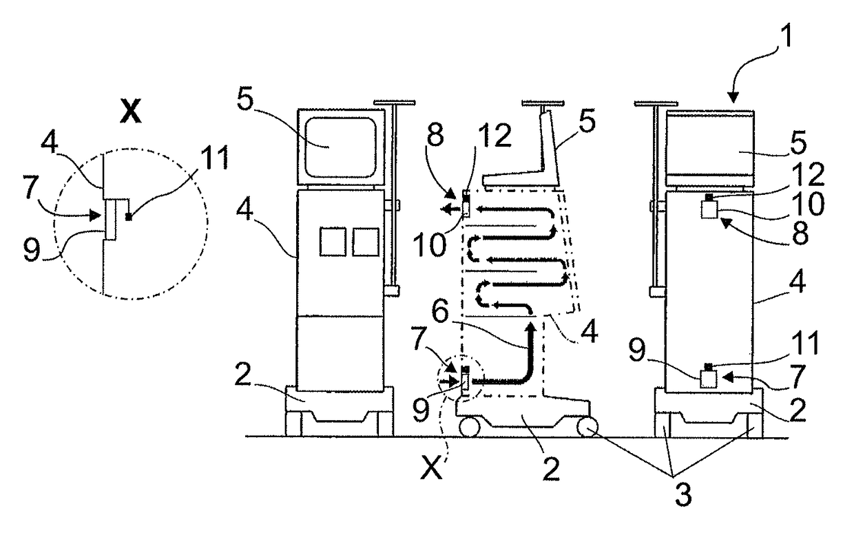
[0028]FIG. 1 shows a dialysis machine 1 according to aspects of the invention in a front view, a rear view and a partly cut side view. Preferably it includes a movable base 2 having rollers 3. On the base a housing 4 hermetically sealed (fluid-tight) against the ambience is arranged which in turn supports a displaying and operating unit 5. In the hermetically sealed housing 4 at least one dialysis fluid system not shown in detail in the Figure is arranged / accommodated. It includes / guides a dialysis fluid which is processed in a known manner with the dialysis fluid system.

[0029]The housing 4 is ventilated, inter alia, for cooling purposes in that airflow is guided through an inlet air aperture 7 into the machine 1, through the housing 4 and out of the housing 1 via an outlet air aperture 8 separate herefrom. In the central representation of FIG. 1 the flow path 6 through the housing 4 is schematically indicated with meander-like arrows. The flow path 6 is configured so that the airfl...


PUM


Abstract

The invention relates to an extracorporeal blood treatment machine, such as a dialysis machine, comprising leakage detection as well as to a method of detecting leakages in the dialysis fluid circuit of a dialysis machine, wherein at least part of the dialysis fluid system to be monitored in terms of leakage is accommodated in a hermetically sealed housing and the housing is or can be ventilated in a controlled manner, and wherein a parameter, such as the air humidity of the air flowing into the housing is compared to a corresponding parameter, preferably air humidity of the air flowing out of the housing.

Description

CROSS REFERENCE TO RELATED APPLICATIONS[0001]This application claims priority to German application DE 10 2014 100 260.1 filed Jan. 10, 2014, the contents of such application being incorporated by reference herein.FIELD OF THE INVENTION[0002]The invention relates to an extracorporeal blood treatment machine, preferably dialysis machine comprising leakage detection and to a method of detecting leakages in the dialysis fluid or dialysate system of a dialysis machine.[0003]Leakages occurring in the dialysis fluid system of a dialysis machine, especially in the balancing circuit of a dialysis machine are critical, as dialysis fluid escaped from the system is missing in the total balance and by reason of the balancing principle a corresponding quantity of fluid is withdrawn from the patient. Such withdrawal of fluid can be critical already in small quantities depending on the patient's weight and / or condition.BACKGROUND[0004]At present it is known to carry out a single pressure test or c...

Claims


Application Information

Patent Timeline
Patent Type & Authority Patents(United States)
IPC IPC(8): A61M1/36A61M1/14
CPCA61M1/3607A61M1/14A61M2205/3327A61M2205/15A61M1/16A61M2205/3331
Inventor RITTER, KAI-UWESCHULZ, OLIVER
Owner B BRAUN AVITUM
Learn More