Slip sheet for transporting goods

Inactive Publication Date: 2008-01-31
TRICKETT HOWARD J
View PDF55 Cites 14 Cited by
  • Summary
  • Abstract
  • Description
  • Claims
  • Application Information

AI Technical Summary

Benefits of technology

[0014] Another configuration of the invention provides a slip sheet tab having a plurality of indentations that make the tab

Problems solved by technology

Those who use slip sheets and slip trays also encounter problems when using known

Method used


Image

  • Slip sheet for transporting goods
  • Slip sheet for transporting goods
  • Slip sheet for transporting goods

Examples


Embodiment Construction

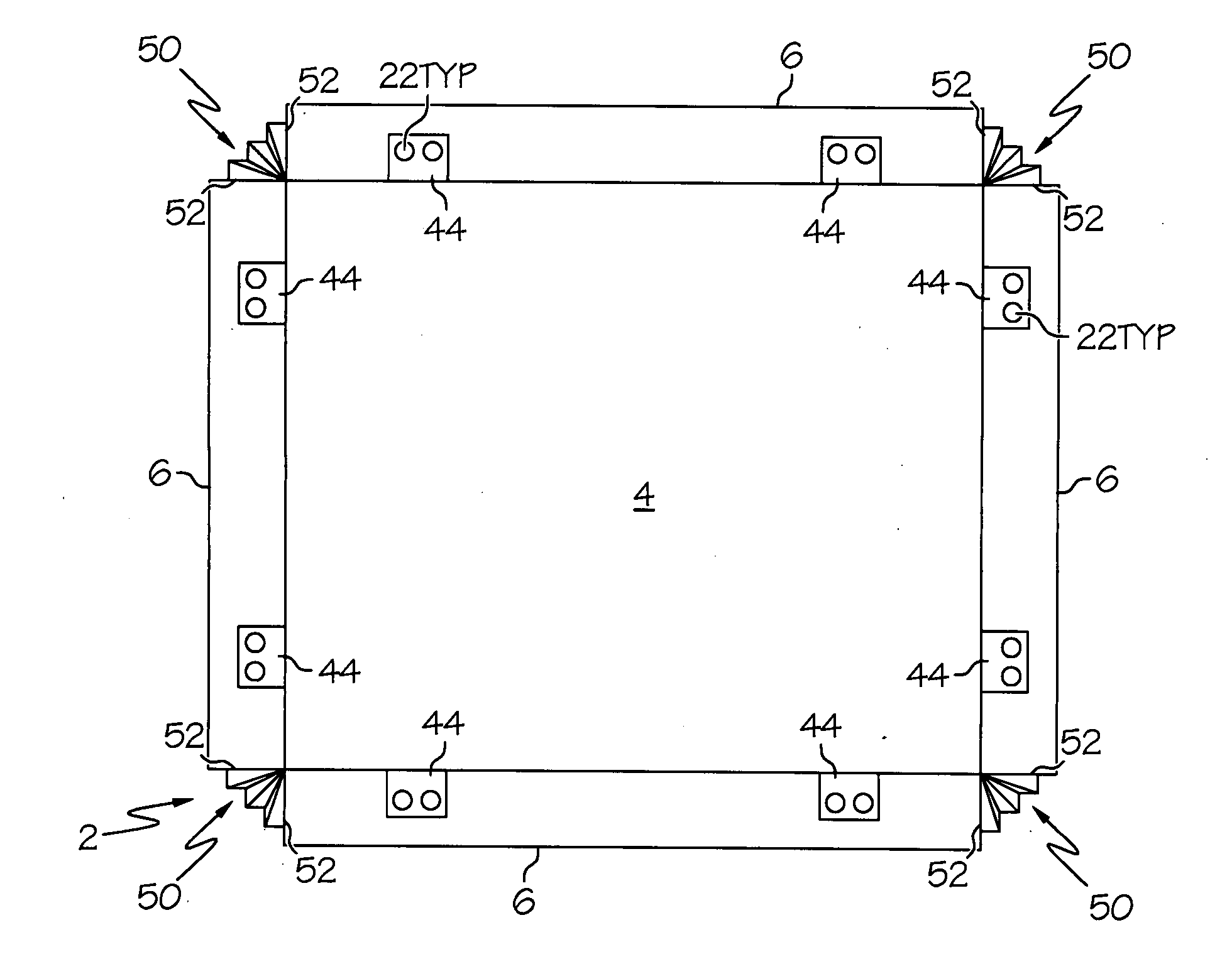
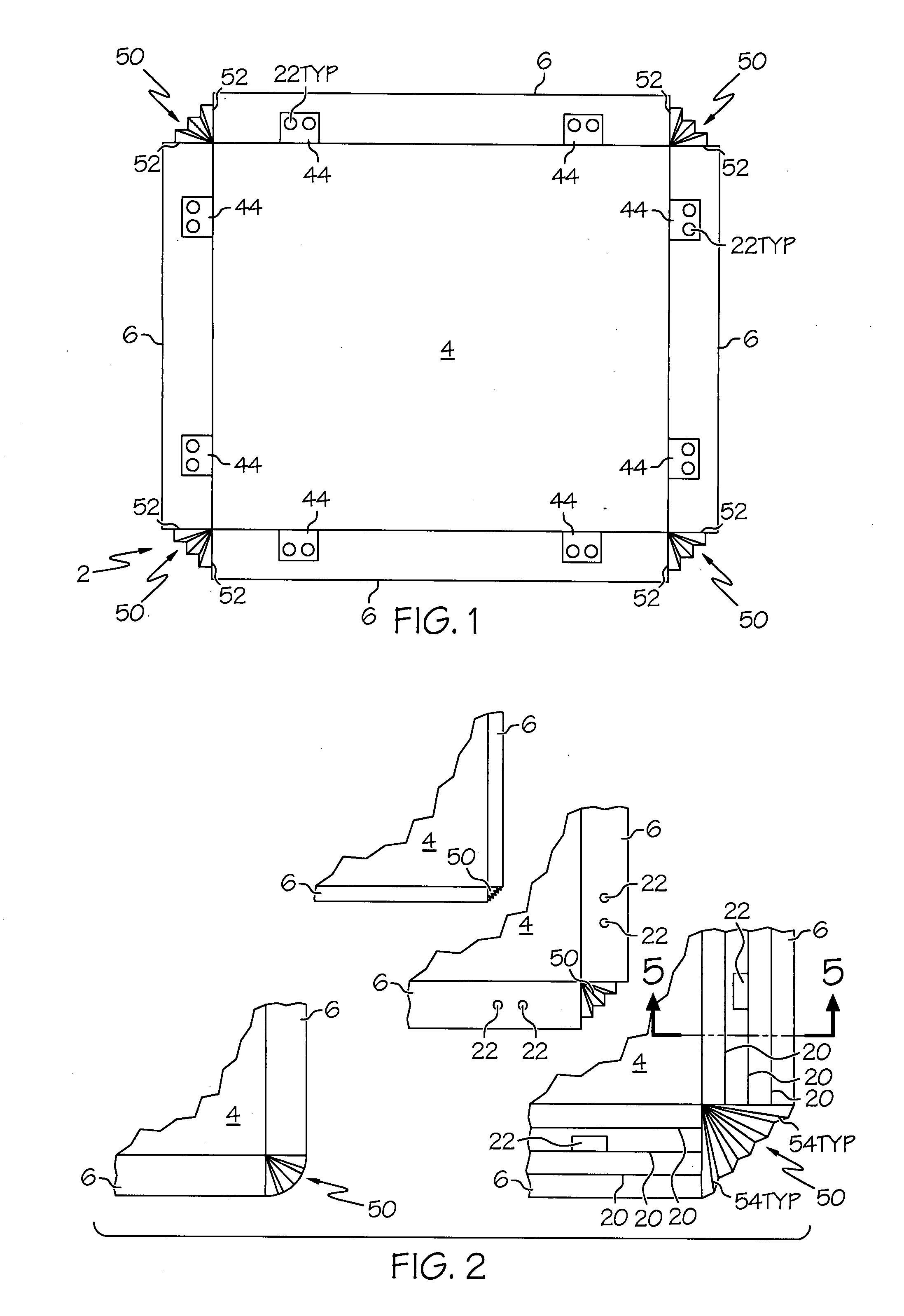
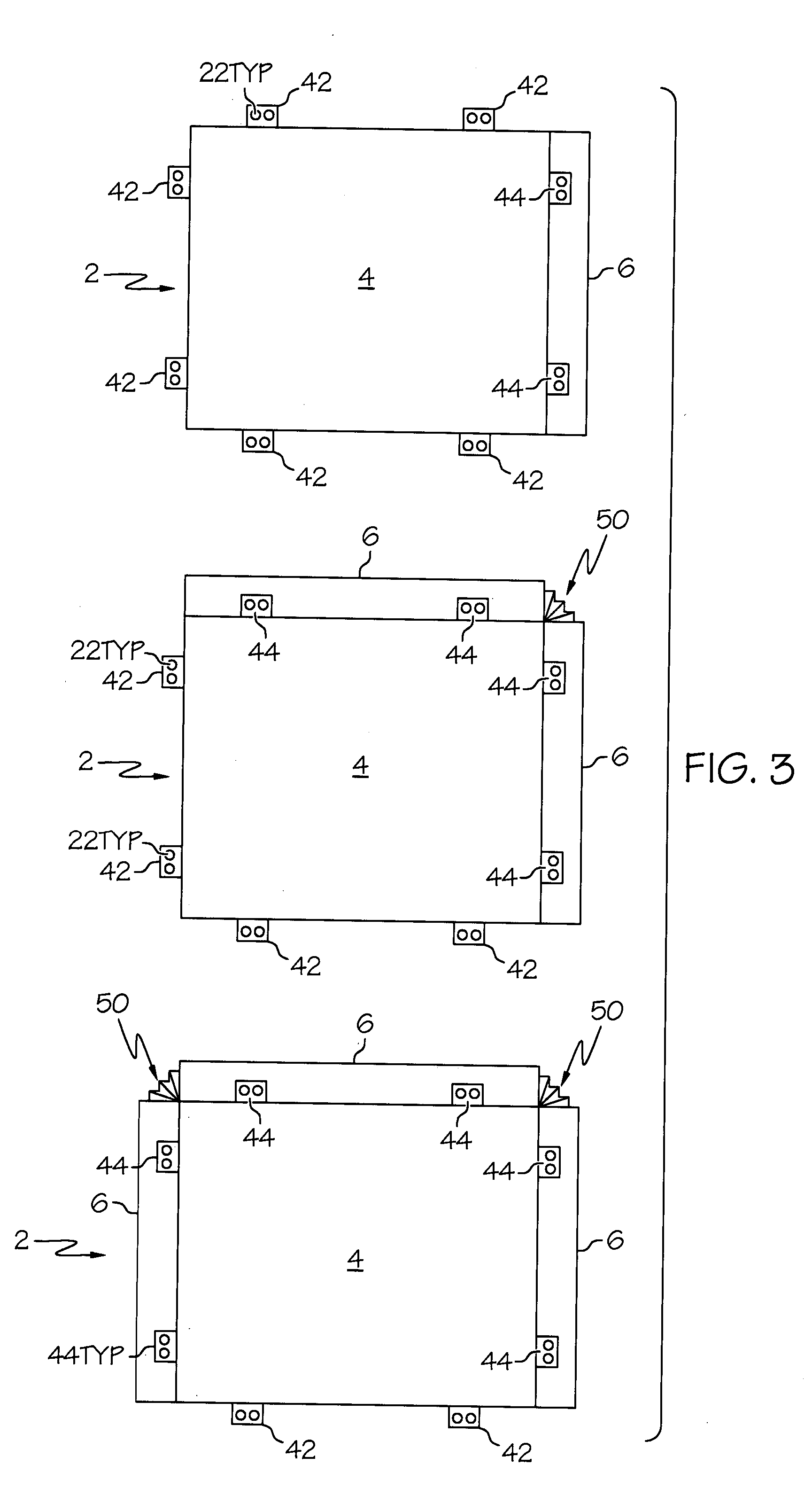
[0027] The slip sheets described below are generally indicted by the numeral 2 in the accompany drawings. Slip sheet 2 generally includes at least a base 4 and a tab 6. For the purpose of providing an example of the invention and the manner in which the invention is used, Slips sheets 2 and slip trays 102 are described in conjunction with the transport of natural rubber bales. The method of transporting natural rubber in crumb and sheet form will be best understood when one first understands the natural rubber itself, which is generally a product of the tree Hevea brasiliensis. While synthetic rubbers have been developed, many applications still require the use of natural rubber, particularly the production of radial tires. The synthetic rubbers were developed during and after World War II, when U.S. companies determined to not be totally dependent on the Pacific Rim sources for natural rubber. However, the natural rubber sources are still a very important economic factor in world r...


PUM


Abstract

A slip sheet for use with unitized loads has a plurality of banding anchors. The banding anchors extend from an edge of the slip sheet or from a portion of the slip sheet tab. The banding anchors may be provided on one, two, three, or four edges of the slip sheet. The banding anchors may be folded up against the side of a unitized load to provide a place for packaging bands to engage the slip sheet. Portions of at least one slip tray sidewall are separated from the remaining sidewall to form flaps that may be folded down to function as tabs that help lift vehicles get under the slip tray.

Description

CROSS REFERENCE TO RELATED APPLICATIONS [0001] This application claims the benefit of U.S. Provisional Patent Application Ser. No. 60 / 833,635 filed Jul. 26, 2006; the disclosures of which are incorporated herein by reference.BACKGROUND OF THE INVENTION [0002] 1. Technical Field [0003] The present invention relates to packaging devices in the nature of slip sheets and slip sheets having sidewalls that are known as slip trays. More particularly, the invention relates to the structures and configurations of the tabs for slip sheets and slip trays. [0004] 2. Background Information [0005] A wide variety of goods are packed into unitized loads for transport. Unitized loads used to be assembled onto wooden pallets. As the use of wooden pallets as diminished for a variety of reasons, the use of slip sheets and slip trays has increased. Those who use slip sheets often wrap the articles that form the unitized load on the slip with stretch wrap and banding. It is desired in the art to be able ...

Claims


Application Information

Patent Timeline
IPC IPC(8): B65D19/06B65D19/00
CPCB65D19/36
Inventor TRICKETT, HOWARD J.
Owner TRICKETT HOWARD J
Why Eureka
Try Eureka