Displaying object orientations on ball joints

a technology of object orientation and ball joint, applied in the field of display of ball joints, can solve the problems of easy visible deviation and comprehensible

Inactive Publication Date: 2008-01-31
BRAINLAB
View PDF13 Cites 14 Cited by
  • Summary
  • Abstract
  • Description
  • Claims
  • Application Information

AI Technical Summary

Benefits of technology

[0012] The surgeon requires clear and comprehensible information on how the position of the implant has changed, for example, with respect to his original planning. The method described herein can separate this required information into an angular deviation (preferred direction/zero angle) and directional information (orientation relationship between the preferred direction and the anatomical directions). Since the angular information is displayed independent of the directional information, it is unambiguou...

Problems solved by technology

Further, displaying the directional information as a circumferential representation with proportio...

Method used


Image

  • Displaying object orientations on ball joints
  • Displaying object orientations on ball joints
  • Displaying object orientations on ball joints

Examples


Embodiment Construction

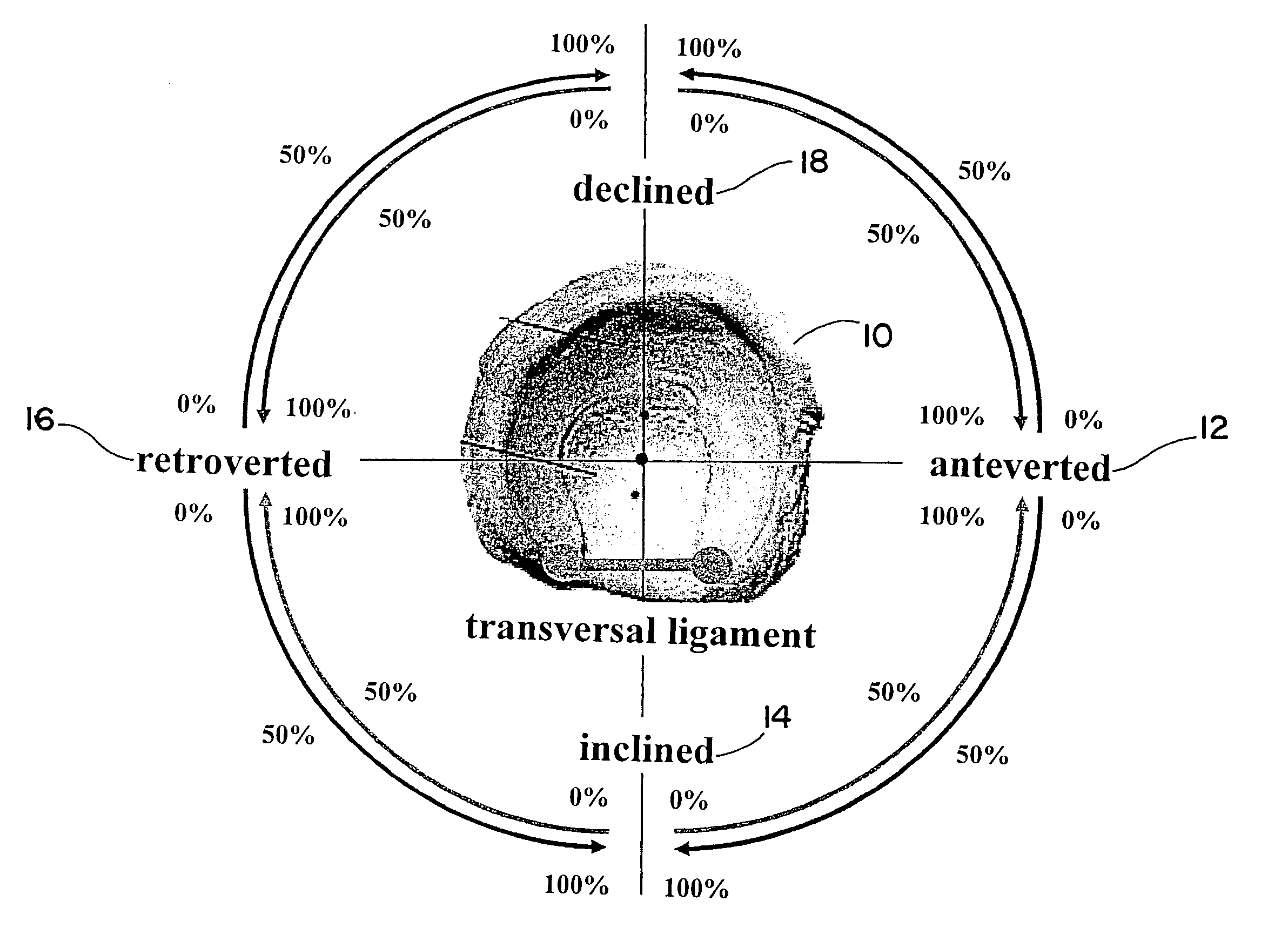
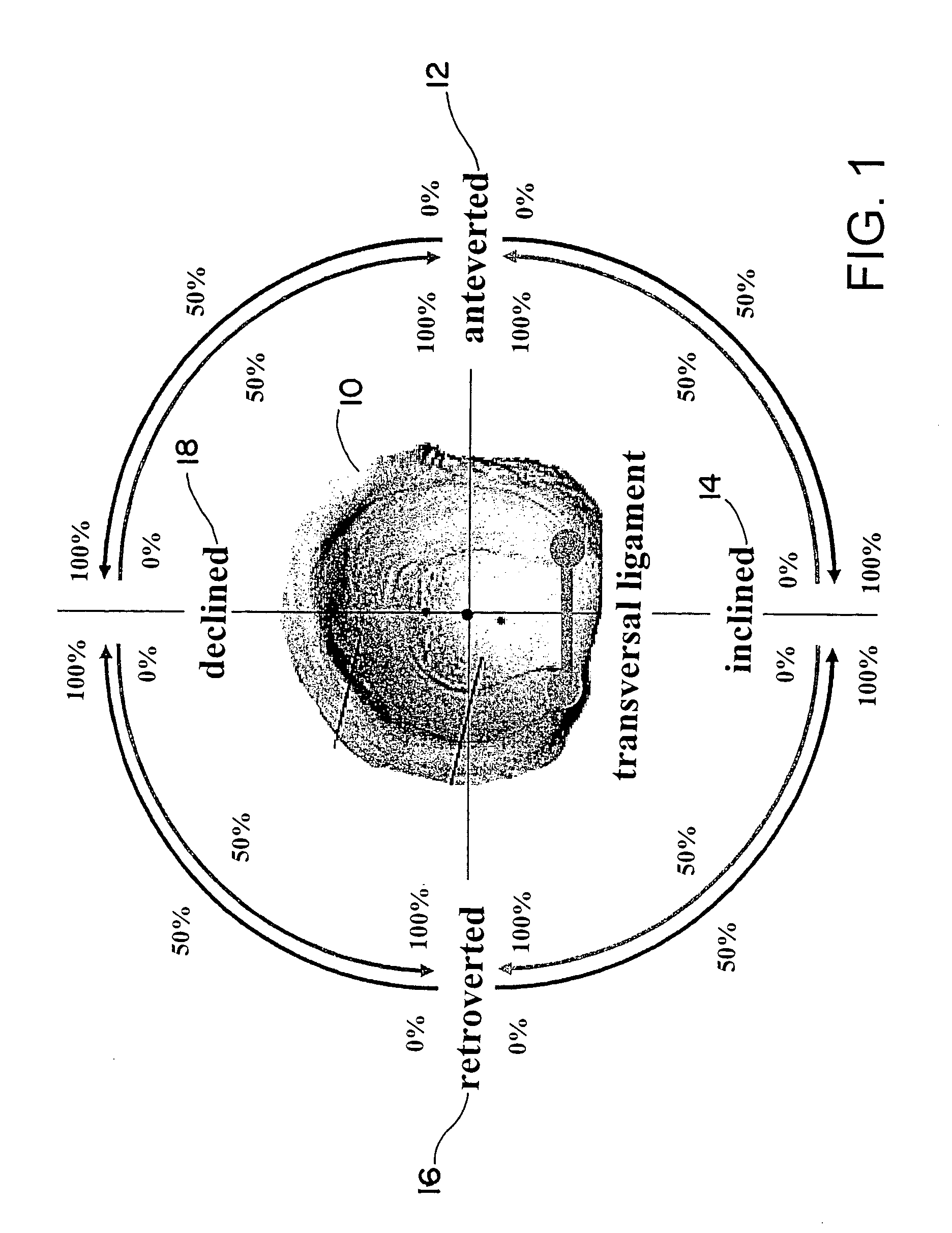
[0034]FIG. 1 illustrates an exemplary hip joint cavity 10 that is localized and / or tracked (positionally detected) using, for example, a medical navigation and / or tracking system. Also shown in FIG. 1 are anatomical directions that are used in conjunction with the method described herein. The two main directions shown in FIG. 1 are the anteversion 12 and the inclination 14, wherein the opposite direction of the anteversion is the retroversion 16 and the opposite direction of the inclination is the declination 18. These two directions are perpendicularly superimposed, and in the circumferential representation (in which proportional values from 0 to 100 percent are given in each of the quadrants) a particular value for anteversion, retroversion, inclination and declination can be assigned to each point on the circumference. The directional information can be displayed along the anatomical directions shown, in the origin plane or perpendicular to the origin plane.

[0035] In the exa...


PUM


Abstract

A method for displaying, in the field of medical technology, an orientation of an object on a ball joint, includes: defining a zero angle projecting out of a joint cavity on the ball joint, wherein directions are defined as anatomical directions; defining a preferred direction of the object, wherein the preferred direction is to be oriented in relation to the zero angle; and graphically displaying the object orientation, wherein a deviation between the preferred direction and the zero angle is displayed as a magnitude, and the relative orientation between the preferred direction and at least one anatomical direction is displayed as a circumferential representation having a proportional value corresponding to the at least one anatomical direction.

Description

RELATED APPLICATION DATA [0001] This application claims priority of U.S. Provisional Application No. 60 / 821,302 filed on Aug. 3, 2006, which is incorporated herein by reference in its entirety.FIELD OF THE INVENTION [0002] The invention relates to the display of ball joints in the context of surgical procedures and, more particularly, to a device and method for displaying the orientation of an object on a ball joint. BACKGROUND OF THE INVENTION [0003] The placement of medical ball joint implants, in particular the insertion of cavity implants for hip joints, can be assisted by medical navigation. Such medical navigation enables the position of the implant and / or the patient (and thus their relative positions) to be determined and tracked. This information can be provided to the physician performing the treatment via visual assistance (e.g., via a screen output). [0004] As an aid for the surgeon, the position of a hip implant can be described by two angles that are output within the ...

Claims


Application Information

Patent Timeline
IPC IPC(8): A61B1/00A61B5/05
CPCA61B19/50A61F2002/4668A61B19/5244A61B19/52A61B34/10A61B34/20A61B90/36
Inventor DICK, ROBERT
Owner BRAINLAB
Why Eureka
Try Eureka