
Server apparatus, terminal device, and method for performing IP multicast communication

a server and terminal technology, applied in the field of internet protocol (ip) multicast communication, can solve the problems of increasing the processing load during ip multicast communication, reducing the cost performance, and unable to perform multicast to a group of terminals based on presence information

Inactive Publication Date: 2008-01-31
KK TOSHIBA
View PDF8 Cites 55 Cited by
  • Summary
  • Abstract
  • Description
  • Claims
  • Application Information

AI Technical Summary

Problems solved by technology

However, in the method according to J. Arkko et al., the terminals need to exchange the encryption key one to one, so that there is a possibility of increasing a processing load during the IP multicast communication.
Because the IP multicast communication can be started only after the key exchange of all the members has completed, it takes longer time to start the communication thereby resulting in lower cost performance.
Furthermore, members of the multicast group are fixed, consequently, therefore, for example, a multicast to a group of terminals that is grouped based on presence information cannot be performed.

Method used


Image

  • Server apparatus, terminal device, and method for performing IP multicast communication
  • Server apparatus, terminal device, and method for performing IP multicast communication
  • Server apparatus, terminal device, and method for performing IP multicast communication

Examples


first embodiment

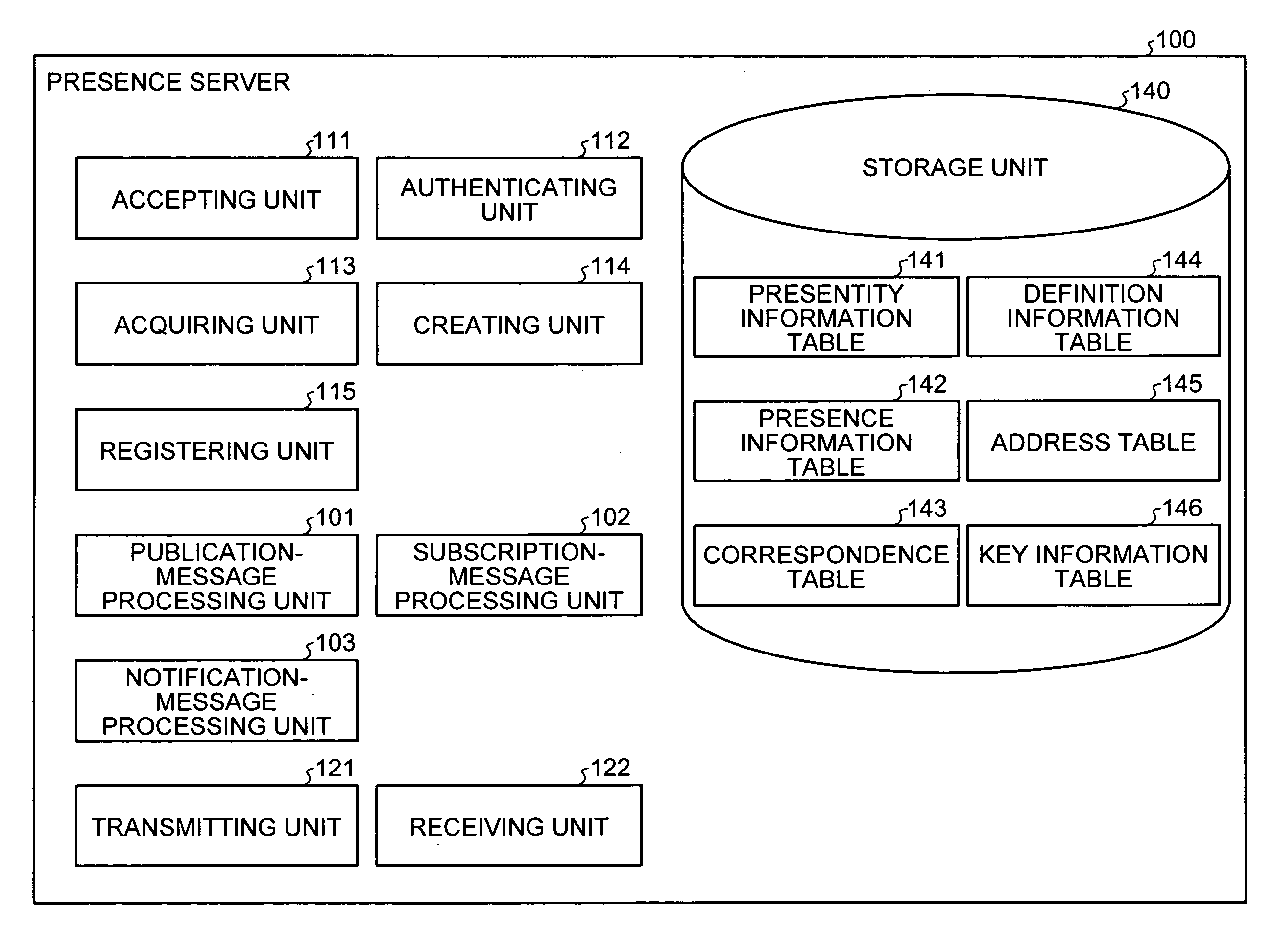
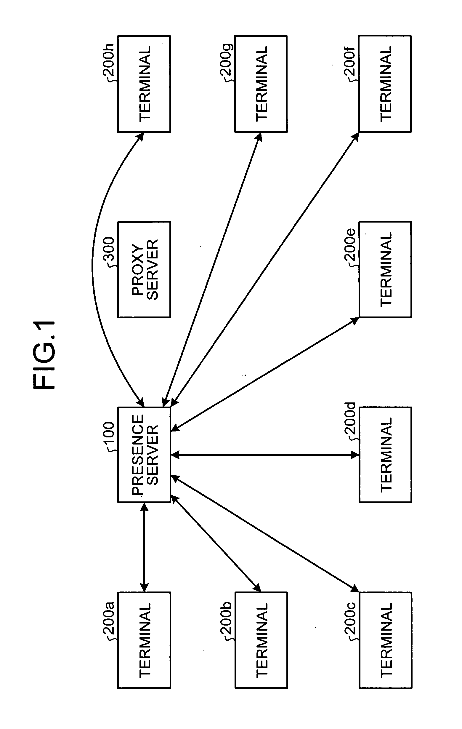
[0040]A server apparatus according to the present invention performs a key exchange process for IP multicast between members of a multicast group in advance by using a presence server function, which was conventionally not used in the IP multicast communication. With this configuration, it is possible to improve cost performance by reducing the time (overhead) until secure IP multicast communication starts in the SIP-based system, which conventionally requires an excessive period because the key is exchanged just before starting the communication.

[0041]Moreover, message transmission for a key exchange protocol and message transmission for presence information are integrated, thereby simplifying the system configuration of the server apparatus and reduce network traffic.

[0042]The presence information is information that indicates a state of a terminal, a user, a group to which the user belongs, and an application program, for example, whether the terminal is available to communicate ...

second embodiment

[0204]A server apparatus according to the present invention transmits a temporarily available encryption key to a terminal that desires a data transmission to a secure multicast group. Because of the temporarily available encryption key, a nonmember terminal can achieve secure IP multicast communication without particular processing, for example, processing for joining the multicast group.

[0205]As shown in FIG. 21, a communication system that includes a presence server 2300, which is the server apparatus according to the second embodiment, differs from the communication system according to the first embodiment shown in FIG. 1 in including a sender terminal 2100z that desires to transmit media data to a multicast group, but does not belong the multicast group.

[0206]Receiver terminals 2100a to 2100h differ from the sender terminal 2100z in belonging to the same multicast group. Hereinafter, the receiver terminals 2100a to 2100h are simply referred to as the receiver terminals 2100.

[02...


PUM


Abstract

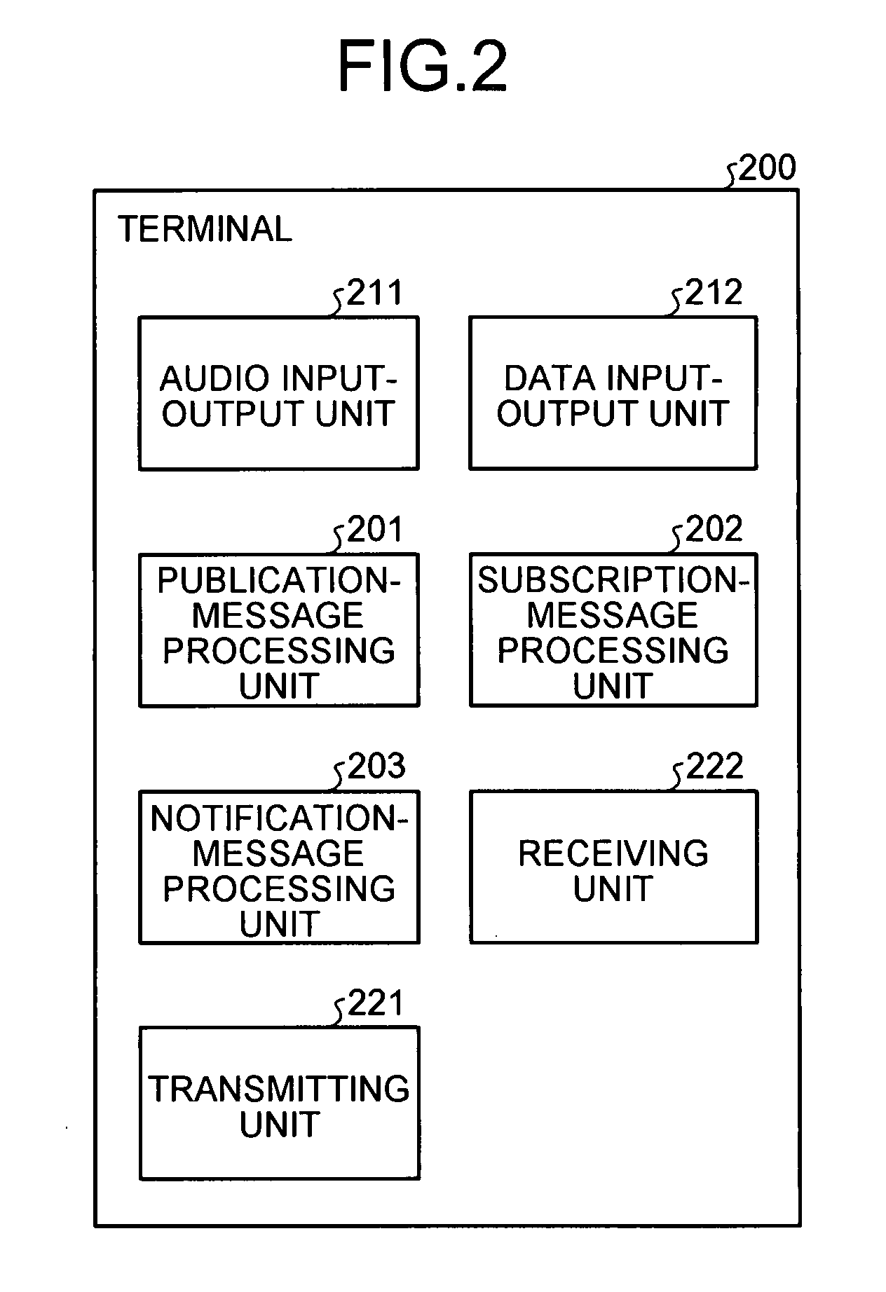
A presence table stores therein presence information. A storage unit stores therein in associated manner a terminal identifier unique each of a plurality of terminals and an encryption key to be used for multicast communication within a multicast group. A receiving unit receives a subscription request message from a first terminal from among the terminals. The subscription message includes the terminal identifier of the first terminal, and a request requesting subscription to the presence information present in the storage unit. An acquiring unit acquires the encryption key from the storage unit by using the terminal identifier of the first terminal. A transmitting unit transmits acquired encryption key to the first terminal.

Description

CROSS-REFERENCE TO RELATED APPLICATIONS[0001]This application is based upon and claims the benefit of priority from the prior Japanese Patent Application No. 2006-203628, filed on Jul. 26, 2006; the entire contents of which are incorporated herein by reference.BACKGROUND OF THE INVENTION[0002]1. Field of the Invention[0003]The present invention generally relates to a technology for performing Internet protocol (IP) multicast communication, and specifically relates to a technology for performing IP multicast communication on systems that operate on session control protocols.[0004]2. Description of the Related Art[0005]Recently, communication systems, such as an Internet telephone system, that uses the session initiation protocol (SIP) that controls multimedia sessions over an IP network, have been developed.[0006]When performing IP multicast communication with a SIP-based communication system, to enhance security, it is desirable that terminals that communicate with each other exchan...

Claims


Application Information

Patent Timeline
IPC IPC(8): H04L9/00H04L9/08H04L12/70
CPCH04L63/065
Inventor TANIZAWA, YOSHIMICHIESAKA, NAOKISHIBATA, TSUTOMU
Owner KK TOSHIBA
Learn More