
Characterization Array and Method for Determining Threshold Voltage Variation

a threshold voltage and array technology, applied in the field of device characterization methods and circuits, can solve the problems of inacceptable design turn time delay and time-consuming and laborious characterization of arrays, and achieve the effect of reducing characterization tim

Inactive Publication Date: 2008-02-07
IBM CORP
View PDF10 Cites 24 Cited by
  • Summary
  • Abstract
  • Description
  • Claims
  • Application Information

AI Technical Summary

Benefits of technology

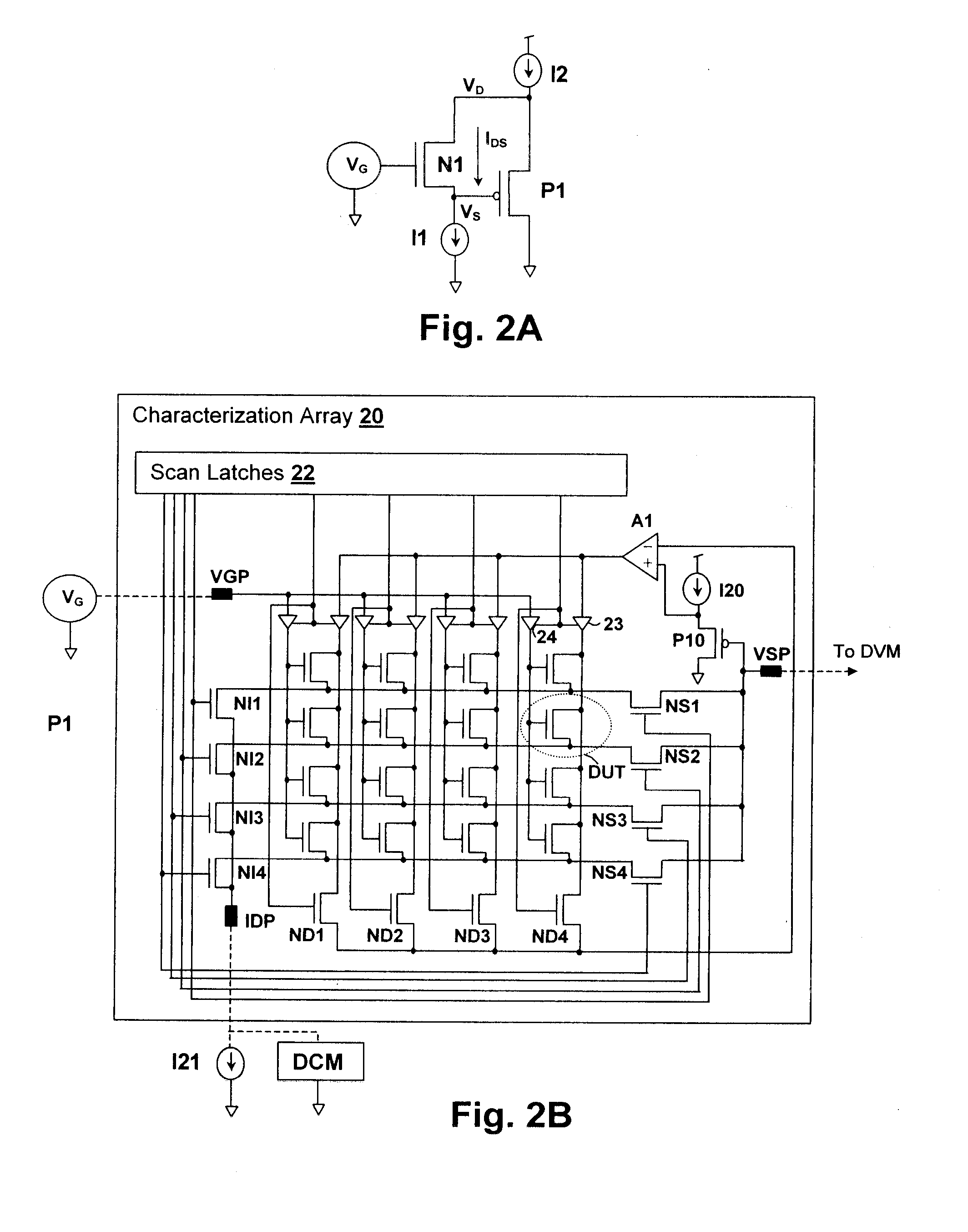
[0011]The measured source voltage values are adjusted according to the determined source-threshold voltage relationship for the fully-characterized device, and the statistics of the threshold voltage are computed from the resulting adjusted values. The result is a statistical description of the distribution of threshold voltages for the array.

Problems solved by technology

However, full characterization of an array is a time-intensive procedure, since the channel current vs. gate voltage curve must be sampled for each individual device to gather threshold voltage statistics that describe the array.
As array sizes increase, the result is unacceptable delays in design turn time, especially when determining factors for a process scaling over a large range of options.

Method used


Image

  • Characterization Array and Method for Determining Threshold Voltage Variation
  • Characterization Array and Method for Determining Threshold Voltage Variation
  • Characterization Array and Method for Determining Threshold Voltage Variation

Examples


Embodiment Construction

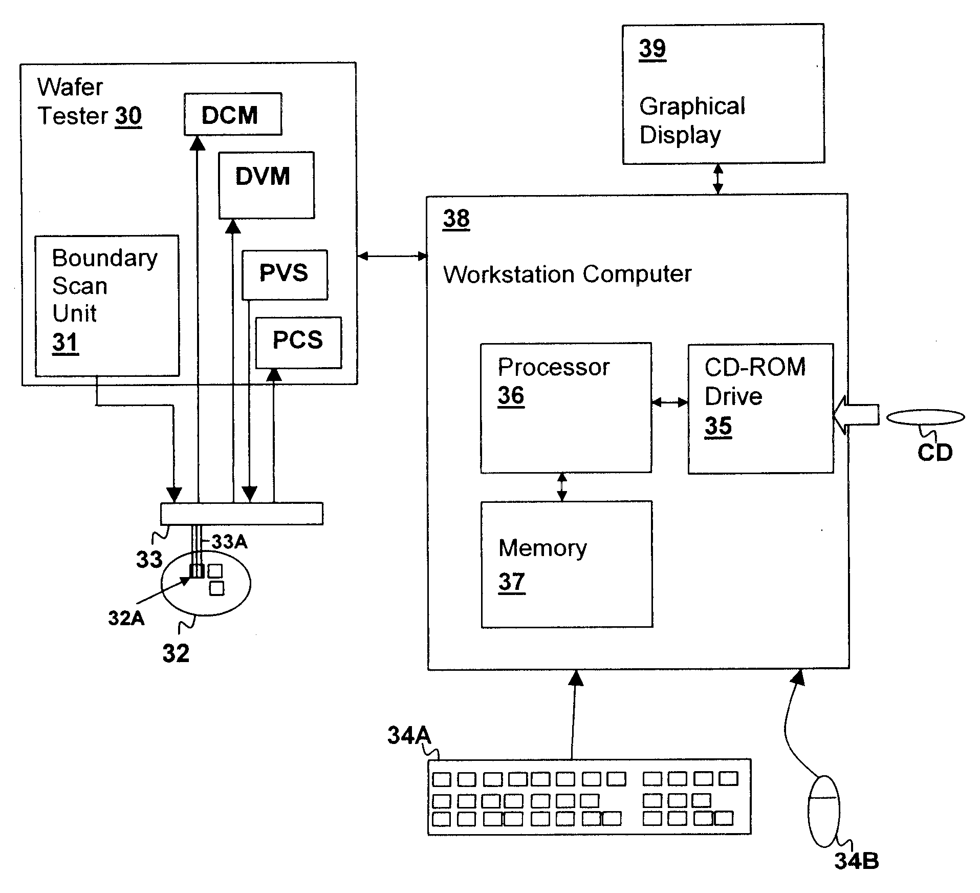
[0017]The present invention relates to a threshold voltage characterization method performed using a characterization array in accordance with an embodiment of the present invention. The method may be a computer-performed method embodied in a computer program having program instructions for carrying out the method. A characterization array is used in the method and may be controlled by computer to provide a measure of threshold voltage for each device in the array. The variation in threshold voltage over the entire array may then be observed from the measurement data. The method of the present invention dramatically reduces the amount of time to characterize the threshold voltage variation within an array, permitting greater flexibility in design decisions associated with process scaling and other process adjustments and in verification of designs.

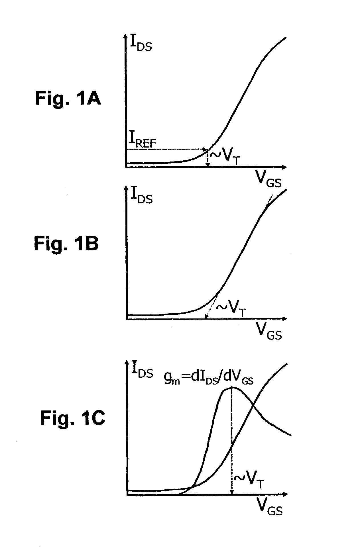
[0018]Referring now to FIGS. 1A-1C, various definitions of threshold voltage as known in the art are shown in graphs of drain-source curr...


PUM


Abstract

A characterization array and method for determining threshold voltage variation rapidly provides accurate threshold voltage distribution values for process verification and improvement. The characterization array includes a circuit for imposing a fixed drain-source voltage and a constant channel current at individual devices within the array. A circuit for sensing the source voltage of the individual device is also included within the array. The statistical distribution of the threshold voltage is determined directly from the source voltage distribution by offsetting each source voltage by a value determined by completely characterizing one or more devices within the array. The resulting methodology avoids the necessity of otherwise characterizing each device within the array, thus reducing measurement time dramatically.

Description

BACKGROUND OF THE INVENTION[0001]1. Field of the Invention[0002]The present invention is related to device characterization methods and circuits, and more particularly to a circuit for determining threshold voltage variation of devices within an array.[0003]2. Description of Related Art[0004]Threshold voltage variation has become significant as processes have shrunk. As process technologies have evolved, random doping fluctuation (RDF) has emerged as a dominant and less controllable factor in device parameter variation. RDF has the statistical effect of generating threshold voltage variations, as the number and location of dopant atoms in the channel region can vary significantly from device to device, even though the overall doping density of a process layer for the entire wafer is well-controlled. Threshold voltage “scatter” is a term used to refer to the spread of threshold voltage.[0005]Software models can be employed to determine the effects of RDF on circuit performance; howev...

Claims


Application Information

Patent Timeline
IPC IPC(8): G01R31/36
CPCG01R31/2621G01R31/2884G01R31/275
Inventor AGARWAL, KANAK B.NASSIF, SANI R.
Owner IBM CORP
Learn More