[0026] In one or more embodiments of the present invention, when an object in front of the radar has been detected, to accurately specify whether that detection is a correct detection from the object actually existing, or an error detection caused by objects to the front-left and front-right of the radar.
[0027] In one or more embodiments of the present invention, a radar device for detecting an object in front of the radar device comprises a plurality of antennas, a position specification means, and an
object detection means. The object is detected based on each reception
signal received by two or more of the plurality of antennas. A position specification means specifies a position of the object by using each reception signal received by the two or more of the plurality of antennas. An
object detection means confirms an existence of the object if the position specified by the position specification means is in a predetermined range. Thus, when the detection object in front of the radar has been detected, i.e., when it is judged that there is a possibility that a detection object exists, whether the detection is the correct detection because the object in the front actually exists, or the error detection due to objects to the front-left and front-right of the radar, can be accurately determined.
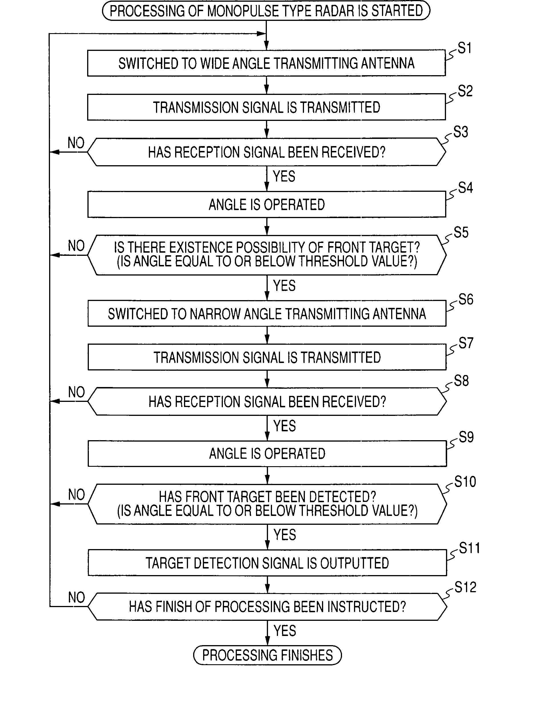
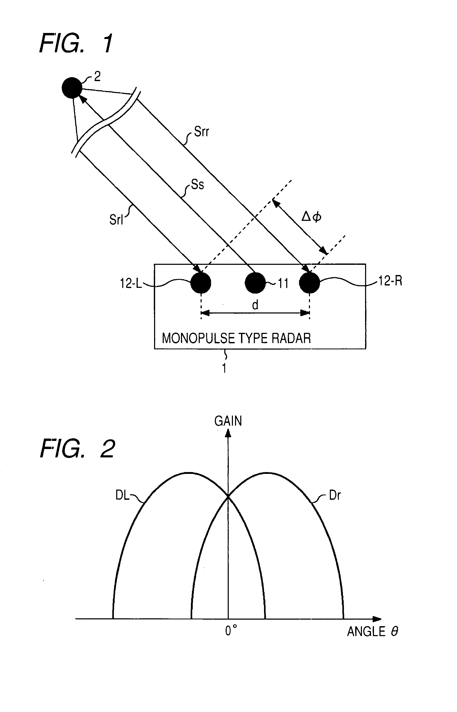
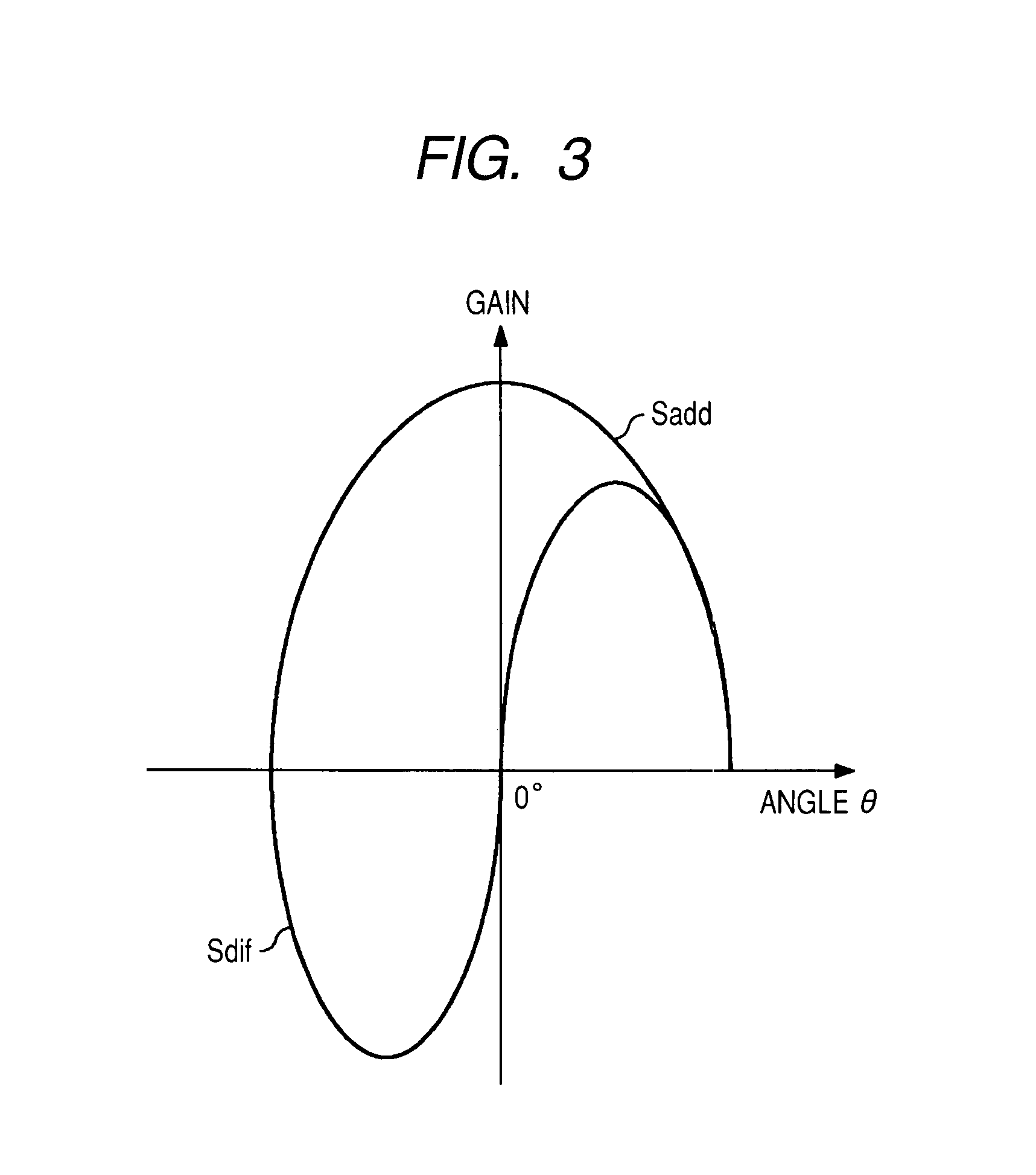
[0032] In one or more embodiments of the present invention, the position specification means operates an angle by a monopulse type and, on the basis of the angle, specifies the position of the object, and the confirmation means operates an angle by a predetermined
system using each reception signal when the reflection signal generated by the second transmission signal being reflected by the object has been received by each of the two or more antennas and, based on a result of that operation, confirms the existence of the object. Thus, one part of a conventional monopulse type sensor can be diverted, and the radar device can be easily realized.
[0035] In one or more embodiments of the present invention, the radar device comprises a velocity-distance operation means operating at least one of a
relative velocity to and a relative distance from the detection object by using at least one part within the each reception signal received by the two or more antennas, and the position specification means specifies the position of the object by using at least one part within an operation result of the velocity-distance operation means, and the confirmation means confirms the existence of the object by using at least one part within the operation result of the velocity--distance operation means. Thus, since a judgment material capable of being utilized for the specification of the position of the object by the specification means and the confirmation of the object by the confirmation means are increased, the detection of the object can be done more accurately.
[0036] In one or more embodiments of the present invention, a detection method in a radar device comprising a plurality of antennas, wherein an object in front of the radar device is detected based on a reception signal received by two or more antennas of the plurality of antennas, comprises the steps of specifying a position of the object by using reception signals received by each of the two or more antennas, and confirming an existence of the object when the specified position is in a predetermined range. Thus, when the detection object in the front has been detected, i.e., when there has been judged that there is the existence possibility of the detection object, it becomes possible to accurately specify whether that detection is the correct detection because the object in the front actually exists, or the error detection due to objects to the front-left and front-right of the radar.
[0037] A radar device according to one or more embodiments of the present invention accurately detects an object in front of the radar. The radar device according to one or more embodiments of the present invention is able reduce error detection. When the object in front of the radar device has been detected, i.e., when the radar device judges that there is a possibility of an existence of the object, it is possible to accurately specify whether that detection is a correct detection because the object in the front actually exists, or an error detection due to objects to the front-left and front-right of the radar.

