Projection display unit

a technology of projection display and display unit, which is applied in the direction of picture reproducers, picture reproducers using projection devices, instruments, etc., can solve problems such as detection accuracy degradation, and achieve the effect of simple configuration

Active Publication Date: 2017-08-17
SONY CORP
View PDF12 Cites 0 Cited by
  • Summary
  • Abstract
  • Description
  • Claims
  • Application Information

AI Technical Summary

Benefits of technology

[0005]In a projector described in PTL 1, image projection by a projection optical system and taking-in of detection invisible light by a detection optical system are performed with a single projection lens. Further, a light valve that produces an image and an imaging device that receives the invisible light are disposed in positions that are optically conjugate with each other. Such a unit configuration allows for accurate object detection without performing a complicated process such as calibration. An interactive device is achievable with a simple configuration.

Problems solved by technology

However, such a unit configuration in which a light source applies invisible light toward a projection surface, for example, may involve an issue that signal intensity based on the applied invisible light is uneven in a light reception surface, leading to degradation of detection accuracy.

Method used


Image

  • Projection display unit
  • Projection display unit
  • Projection display unit

Examples


embodiment

1. Embodiment

[Configuration]

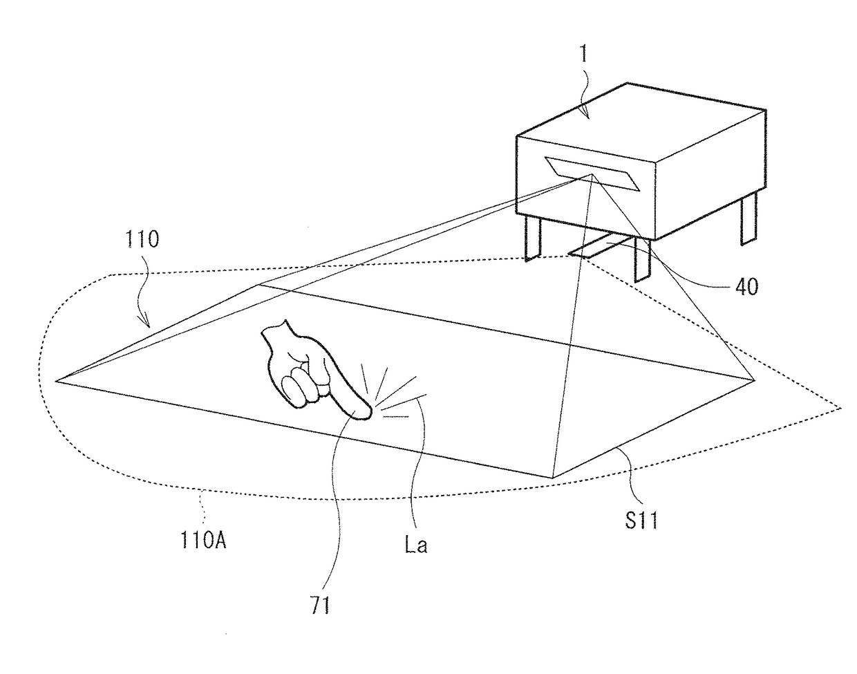
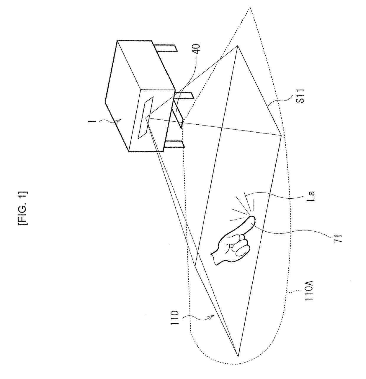
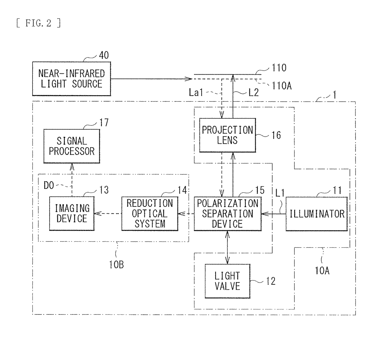
[0040]FIG. 1 illustrates an appearance and a usage state of a projection display unit (a projection display unit 1) according to one embodiment of the disclosure. FIG. 2 illustrates a functional configuration of the projection display unit 1. The projection display unit 1 may be, for example, a projector of a type (a so-called ultra-short throw type) that projects an image onto the vicinity of its own while being placed on a flat surface such as a top of a table (or while being mounted on, for example, a wall surface). The projection display unit 1 may also have a function of actively performing object detection in addition to the image display function. As illustrated in FIG. 1, a predetermined input operation is allowed to be performed by performing an operation in a way such as touching a displayed image with a finger (an indicator 71) in a projection region (a projection region S11) onto which an image is projected, as will be described in detail late...


PUM


Abstract

A projection display unit (1) includes a projection optical system (10A), a polarization separation device (15), and a detection optical system (10B). The projection optical system includes an illuminator (11), a projection lens (16), and a light valve (12) that modulates illumination light supplied from the illuminator on the basis of an image signal, and outputs the modulated illumination light toward the projection lens. The polarization separation device (15) is disposed between the light valve and the projection lens. The polarization separation device separates entering light into a first polarized component and a second polarized component, and outputs the first polarized component and the second polarized component in respective directions that are different from each other. The detection optical system includes an imaging device (13) and a reduction optical system (14). The imaging device is disposed in a position that is optically conjugate with a position of the light valve. The reduction optical system is disposed between the imaging device and the polarization separation device. The imaging device receives, via the projection lens and the polarization separation device, light based on detection invisible light. A transmittance adjuster is provided between the polarization separation device and the imaging device. The transmittance adjuster adjusts transmittance of at least part of a bundle of passing light rays derived from the invisible light.

Description

TECHNICAL FIELD[0001]The disclosure relates to a projection display unit having a detection function.BACKGROUND ART[0002]In recent years, for example, a smartphone or a tablet terminal may include a touch panel, thereby allowing, for example, page-turning, zooming-in, or zooming-out of an image displayed on a screen to be performed by an intuitive pointing operation. On the other hand, as a display unit that performs display by projecting an image onto a screen, a projector (a projection display unit) has been long known. There is proposed a technology to add a detection function such as that of a touch panel to the projector, for example, as disclosed in PTLs 1 and 2.CITATION LISTPatent Literature[0003]PTL 1: Japanese Unexamined Patent Application Publication No. 2007-52218[0004]PTL 2: Japanese Unexamined Patent Application Publication No. 2003-44839SUMMARY OF INVENTION[0005]In a projector described in PTL 1, image projection by a projection optical system and taking-in of detectio...

Claims


Application Information

Patent Timeline
Patent Type & Authority Applications(United States)
IPC IPC(8): G06F3/042G03B21/20G02B13/16G02B13/00G02B27/28H04N9/31
CPCG06F3/0425G02B27/283G03B21/208G02B13/16G02B13/0095H04N9/3197G02B27/0905G02B27/0966G03B17/17G03B17/54G03B21/2073H04N9/3167H04N9/3179H04N9/3194
Inventor KANEDA, KAZUMASA
Owner SONY CORP
Why Eureka
Try Eureka