
Conference bridge server

a bridge server and conference technology, applied in special services for subscribers, telephone service networks, electrical equipment, etc., can solve the problems of poor voice quality of participants speaking in the common conference room

Active Publication Date: 2008-02-07
RPX CORP
View PDF24 Cites 40 Cited by
  • Summary
  • Abstract
  • Description
  • Claims
  • Application Information

AI Technical Summary

Benefits of technology

[0012]The invention provides an elegant solution for the problem if there are more participants than microphones. By using laptop computers as individual microphones, the participants at a remote location can hear properly what is said in the common conference room because each participant is very close to his own microphone. Besides, there is no need that microphones of the hardware conferencing phone are passed around in the common conference room so that each speaker can be heard correctly.
[0013]A conferencing tool is able to differentiate input signals originating from microphones at a specific location from input signals orginiating from microphones at another location. Thus, parameters of echo cancellation may be optimized for the microphones at a specific location to prevent echo due to the mixed audio input and output. The availability of a separate microphone for each participant and the improved echo cancellation result in a better media quality at remote locations.

Problems solved by technology

In conference calls, where some participants share a common conference room while other participants are at remote locations, the voice quality from participants speaking in the common conference room is often poor when using a standard conference phone with handsfree feature.

Method used


Image

  • Conference bridge server
  • Conference bridge server
  • Conference bridge server

Examples


Embodiment Construction

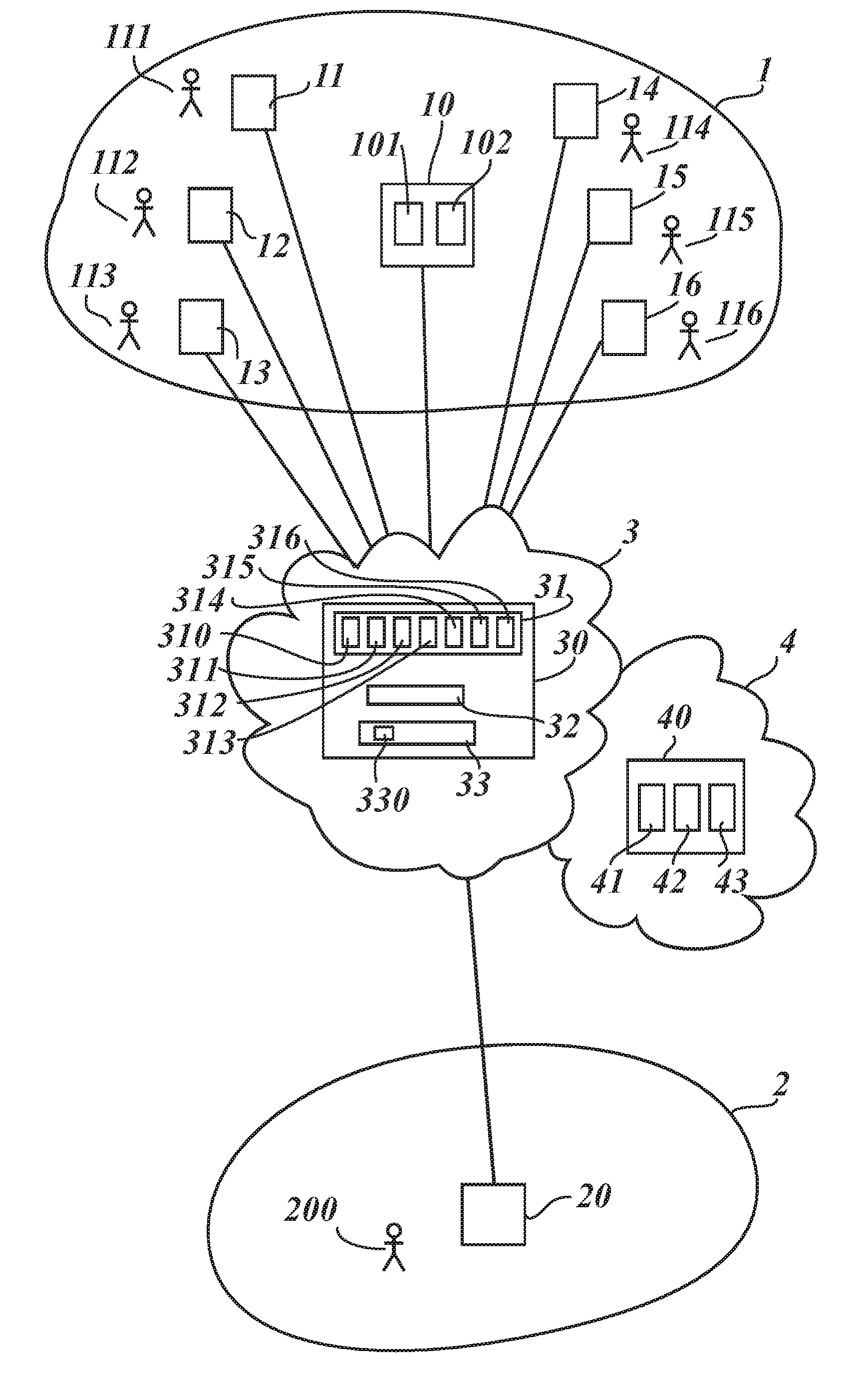
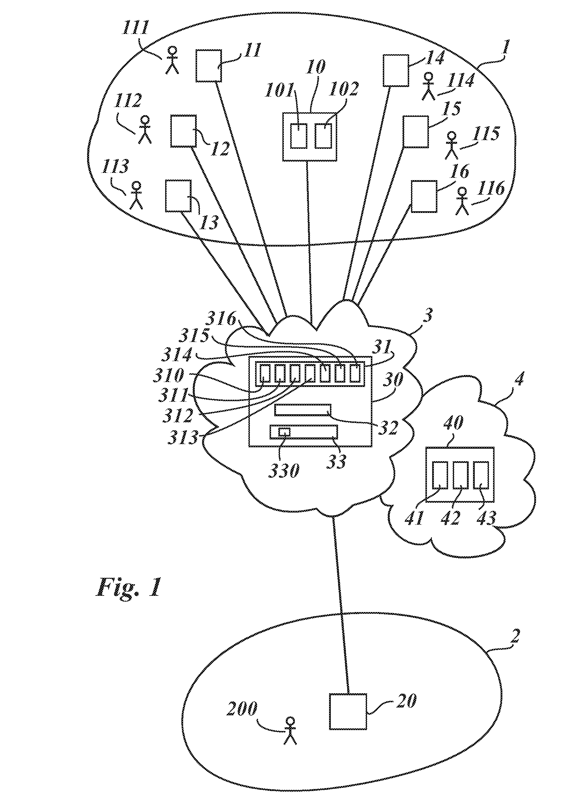
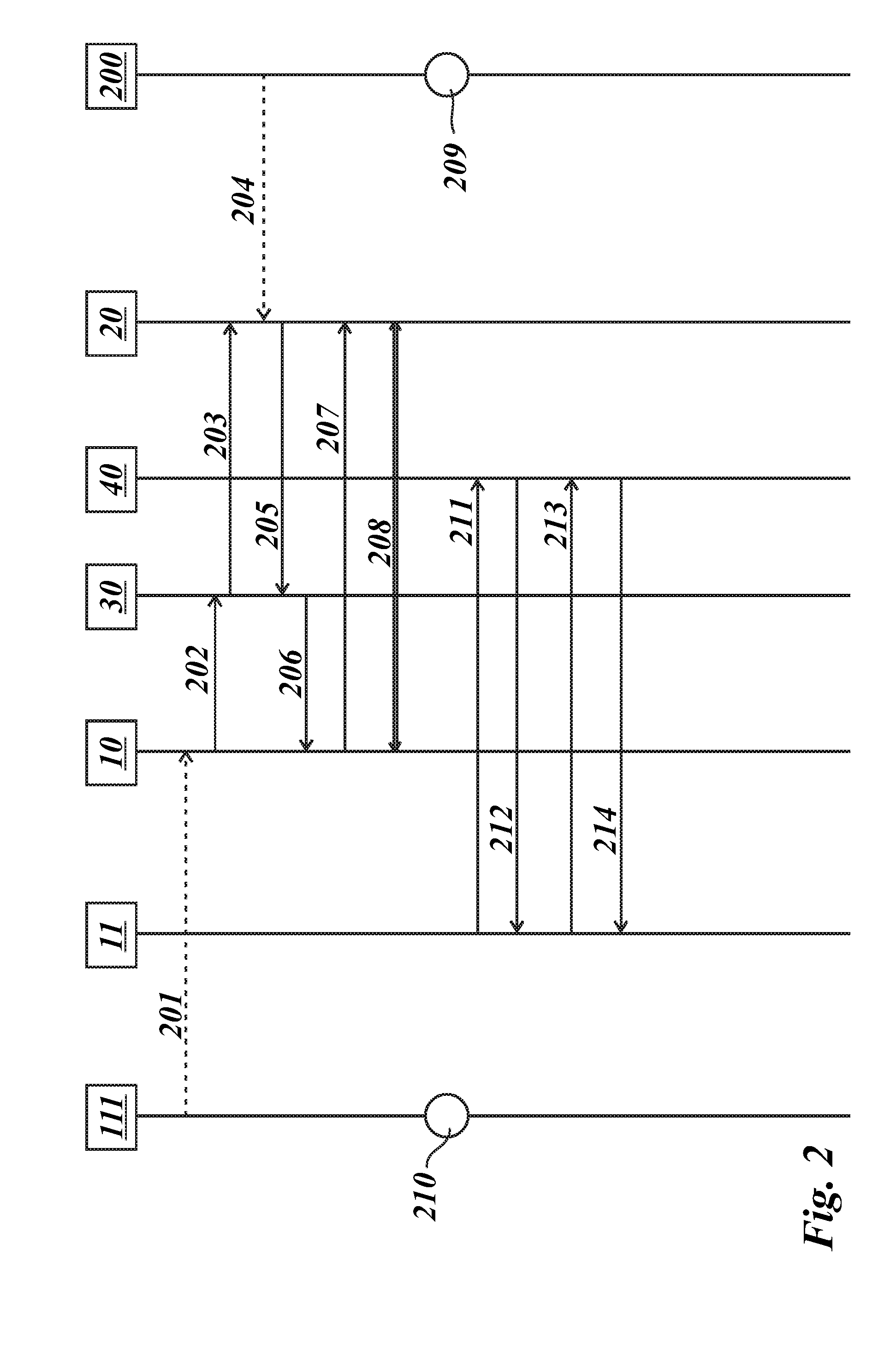
[0031]FIG. 1 shows a conference call system comprising a hardware conference phone 10 with multiple microphones 101 and a loudspeaker 102 at a first location 1, a telecommunications network 3 with a conference bridge server 30, a virtual conference phone unit 40 accessible via another network 4, and a remote telephone 20 at a second location 2. The virtual conference phone unit 40 may be provided and / or installed by a web server where web server here means web technology and not necessarily public internet location. The virtual conference phone unit 40 may be in the Internet but it may be found in a corporate network as well. Thus, the other network 4 may be the public Internet but it may be a corporate network.

[0032]The hardware conference phone 10 is used for a conference call by participants 111 to 116 at the first location 1. The participants 111 to 116 wish to communicate with another participant 200 using the remote telephone 20 at the second location 2. Each of the participan...


PUM


Abstract

The invention concerns a conference bridge server (30) for establishing a conference telephone call, and a corresponding method and a computer program product. The conference bridge server (30) comprises input and output means (31, 33) for a plurality of communication connections connecting conference terminals (11 to 16, 20) with the conference bridge server (30) and a conference core (32) for distributing input signals from conference terminals (11 to 16, 20) to at least some of the remaining conference terminals (11 to 16, 20). The conference bridge server (30) comprises means for issuing a special address to be utilized, by one or more participants (111 to 116) at a first location (1) using a common conference phone (10), to connect one or more laptop computers (11 to 16) as additional conference terminals (11 to 16). Said conference core (32) is programmed to distribute, in said conference call, input signals from conference terminals (11 to 16) connected via said special address to conference terminals (20) assigned to other participants (200) at one or more other locations (2). At the same time, said conference core (32) is programmed to redirect output signals destined for conference terminals (11 to 16) connected via said special address to said common conference phone (10).

Description

[0001]The invention is based on a priority application EP 06 291 250.6 which is hereby incorporated by reference.TECHNICAL FIELD [0002]The present invention relates to a method of establishing telephone conference calls, and a conference bridge server and a computer program product to execute said method.BACKGROUND OF THE INVENTION [0003]Conference calls play a significant role in today's business life. In conference calls, where some participants share a common conference room while other participants are at remote locations, the voice quality from participants speaking in the common conference room is often poor when using a standard conference phone with handsfree feature.[0004]Professional conference rooms exist where each participant has their own input device, e.g., their own microphone, while audio output goes to a common room loudspeaker. In addition, conference systems are known that use desktop or laptop computers as audio and / or video terminals and that have a bridge serv...

Claims


Application Information

Patent Timeline
IPC IPC(8): H04M3/42
CPCH04M3/56H04M7/006H04M3/562
Inventor REY, JEAN-FRANCOIS
Owner RPX CORP
Learn More