
Graft ligament strand tensioner

a graft ligament and tensioner technology, applied in the field of medical devices, can solve the problems of difficult to reliably tension each ligament strand to an equal tension, inability to achieve desired tension, and inability to reliably attach the weight to the various graft ligament strands

Inactive Publication Date: 2008-02-07
ENTERPRISES HLDG INC
View PDF8 Cites 152 Cited by
  • Summary
  • Abstract
  • Description
  • Claims
  • Application Information

AI Technical Summary

Problems solved by technology

The tension on each graft ligament strand may be applied by hand, one ligament at a time, but this approach is relatively time-consuming and makes it difficult to reliably tension each ligament strand to an equal, desired tension.
Furthermore, this approach is generally impractical where the several graft ligament strands are to be secured to the host bone using a single fastener or anchor.
While this approach provides a known, equal tension on each graft ligament strand, it is generally fairly time-consuming to attach the weights to the various graft ligament strands.
Furthermore, it can be awkward for the surgeon to work around the weights, which are hanging down from the free ends of the graft ligament strands, particularly at the point in the procedure when the surgeon is securing the graft ligament strands to the host bone (e.g., to the tibia, in the case of an ACL reconstruction).
However, applying tension equally to each of the several graft ligament strands can be complicated in situations where the graft ligament strands are positioned and tensioned using sutures extending from the strands, since the sutures are often not the same length.

Method used


Image

  • Graft ligament strand tensioner
  • Graft ligament strand tensioner
  • Graft ligament strand tensioner

Examples


Embodiment Construction

First Preferred Embodiment of the Novel Tensioner

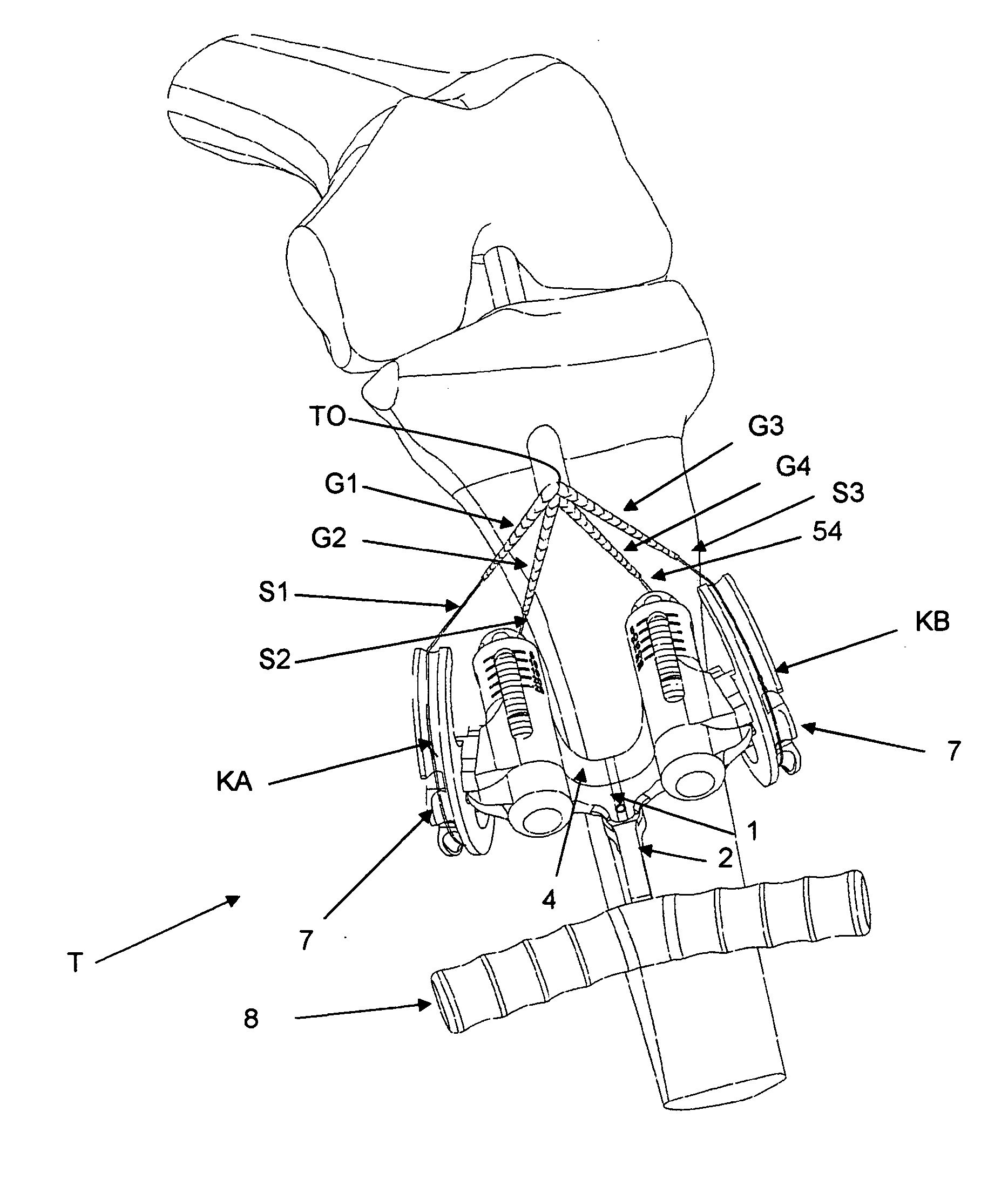
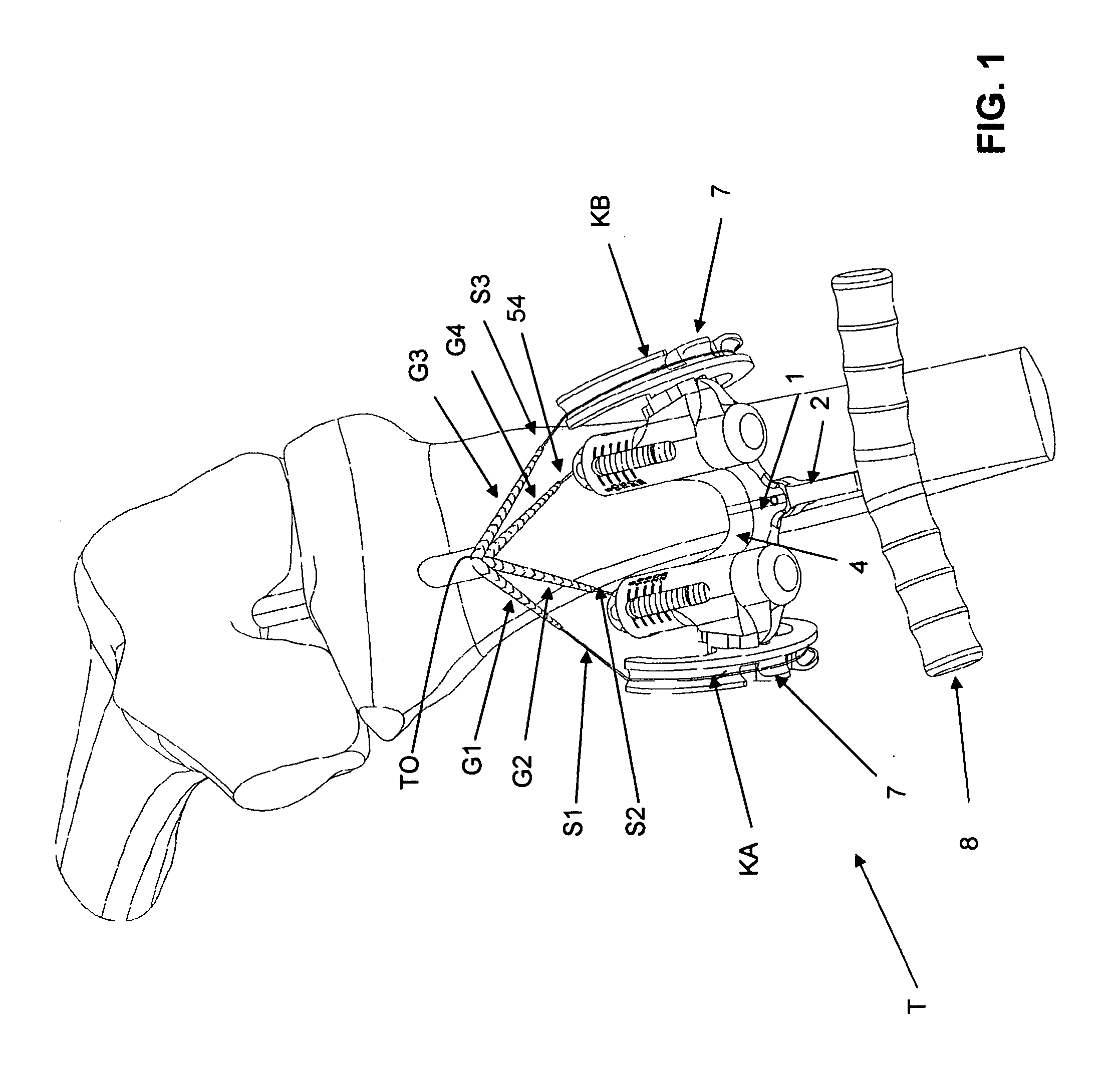
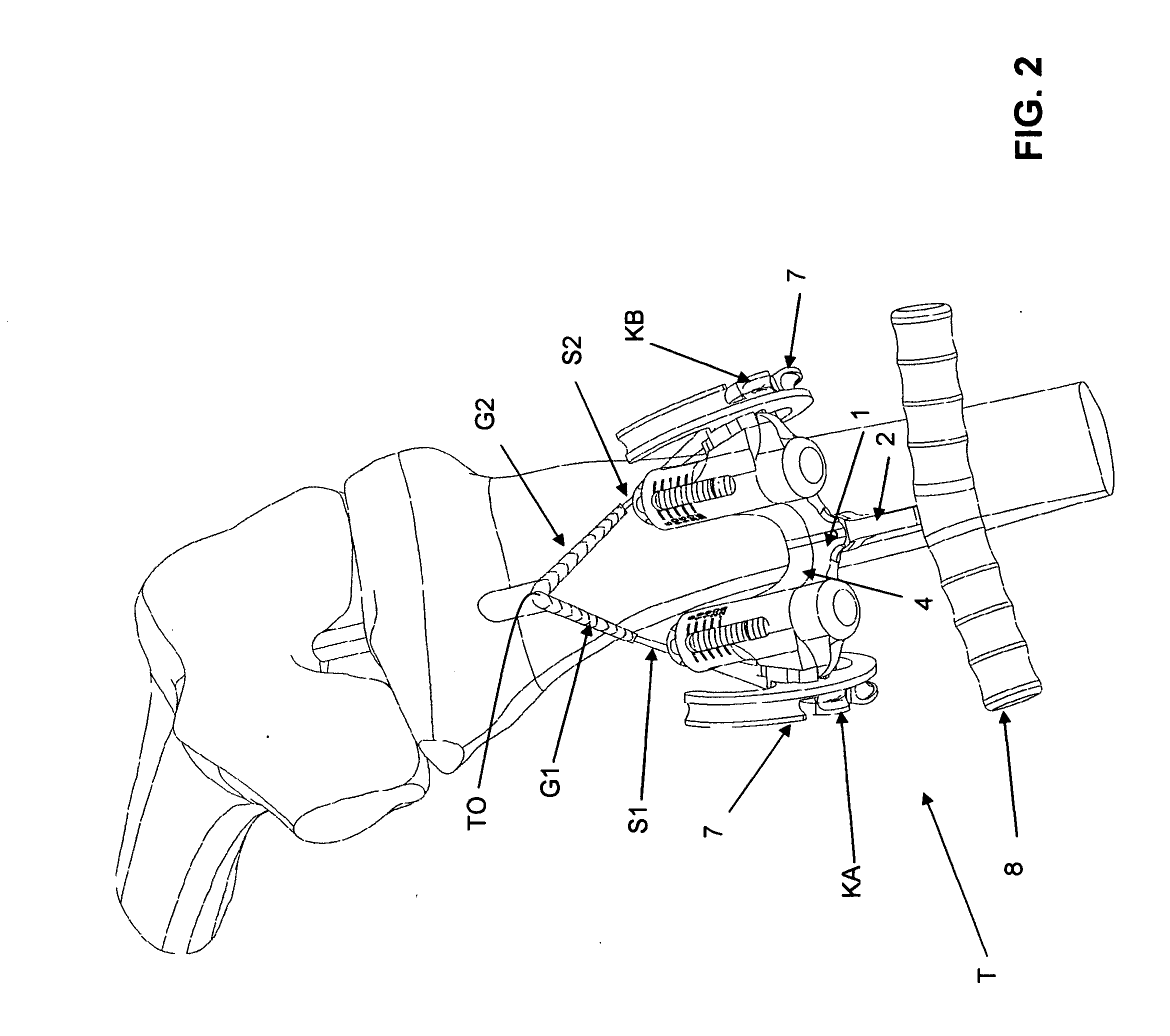
[0028] Looking first at FIGS. 1-11, there is shown a first preferred embodiment of the novel graft ligament strand tensioner. More particularly, the novel graft ligament strand tensioner T generally comprises a handle body 1 (FIG. 6), a handle beam 2, a pair of slide rails 3 (FIG. 11), a slide body 4, a pair of compression springs 5 (FIG. 11), a handle pivot pin 6, a pair of suture rails 7, a pair of handle grips 8, a pair of retaining pins 9 (FIG. 3), and a pair of retaining pin springs 10 (FIG. 11), all of which are assembled together in the manner shown in the drawings, and as hereinafter discussed, so as to form the complete tensioner T. Tensioner T may be used to position and tension a plurality (e.g., four or two) graft ligament strands in the course of effecting a ligament (e.g., an ACL) reconstruction. By way of example but not limitation, FIG. 1 shows tensioner T being used in a four-strand ligament reconstruction, and FIG. ...


PUM


Abstract

A graft ligament strand tensioner comprising: a body; and a pair of suture rails connected to the body, wherein each suture rail comprises a grooved outer channel for receiving a suture loop and a central mandrel for receiving a suture loop, wherein the separation of a suture loop received by the grooved outer channel is larger than the separation of a suture loop received by the central mandrel. A graft ligament strand tensioner comprising: a body; and a plurality of cleats connected to the body, wherein each of the cleats is configured to releasably secure a length of suture. A graft ligament strand tensioner comprising: a body; at least two suture-engaging elements for releasably engaging a pair of sutures, the at least two suture-engaging elements being connected to the body, in spaced-apart fashion, symmetrically about a center axis of the body; and a handle pivotally connected to the body, such that the handle can be laterally positioned relative to the longitudinal axis of the body.

Description

REFERENCE TO PENDING PRIOR PATENT APPLICATION [0001] This patent application claims benefit of pending prior U.S. Provisional Patent Application Ser. No. 60 / 816,407, filed Jun. 26, 2006 by Peter Marshall et al. for GRAFT LIGAMENT STRAND TENSIONER (Attorney's Docket No. SCAN-21 PROV), which patent application is hereby incorporated herein by reference.FIELD OF THE INVENTION [0002] This invention relates to medical devices in general, and more particularly to devices for simultaneously positioning and tensioning, to a selected tension, a plurality of graft ligament strands. BACKGROUND OF THE INVENTION [0003] It is known in the art to use four graft ligament strands, such as two gracilis strands (e.g., a gracilis tendon doubled over) and two semitendinosus strands (e.g., a semitendinosus tendon doubled over), in the reconstruction of an anterior cruciate ligament (ACL). It is further known in the art to use other numbers of graft ligament strands, such as one, two or three strands, in ...

Claims


Application Information

Patent Timeline
IPC IPC(8): A61F2/08
CPCA61B17/8869A61F2002/0882A61F2/0805A61B2017/0496
Inventor MARSHALL, PETERHUBBARD, DENNIS
Owner ENTERPRISES HLDG INC
Learn More