Artificial facet joint

a facet joint and artificial technology, applied in the field of spinal instrumentation, can solve the problems of affecting the normal forward curvature of the spine, pain, neurological dysfunction, and limited use of capping techniques, and achieve the effect of facilitating the control of the movement of adjacent vertebra

Inactive Publication Date: 2006-07-06
DEPUY SPINE INC (US)
View PDF99 Cites 267 Cited by
  • Summary
  • Abstract
  • Description
  • Claims
  • Application Information

AI Technical Summary

Benefits of technology

[0008] While the first and second members can have a variety of configurations, in one exemplary embodiment the first member can be substantially U-shaped with opposed arms extending from a central portion, and the second member can be substantially Y-shaped with opposed arms extending from a terminal end of the extension rod. In use, each arm on the first and second members can be adapted to be received within a receiving head of a bone engaging element, such as a bone screw, to attach each arm to a vertebra. The device can also include at least one compressive element positioned between the central portion of the first member and the central portion of the second member, and at least one compressive element positioned between the central portion of the second member and a terminal end of the extension rod. The compressive element(s) can be adapted to facilitate controlled movement of the adjacent vertebrae.

Problems solved by technology

Subsequent surgery may also be required after a laminectomy, as a laminectomy predisposes the patient to instability and may lead to post-laminectomy kyphosis (abnormal forward curvature of the spine), pain, and neurological dysfunction.
As a result, additional stress may be applied to the adjoining levels, thereby potentially leading to further damage.
Capping techniques, however, are limited in use as they will not remove the source of the pain in osteoarthritic joints.
Caps are also disadvantageous as they must be available in a variety of sizes and shapes to accommodate the wide variability in the anatomical morphology of the facets.
Caps also have a tendency to loosen over time, potentially resulting in additional damage to the joint and / or the bone support structure containing the cap.
However, aligning two articulating rigid surfaces for facet replacements can be very difficult given the variations in patient anatomy and various motion required (i.e., flexion, extension, lateral bending, and translations).

Method used


Image

  • Artificial facet joint
  • Artificial facet joint
  • Artificial facet joint

Examples


Embodiment Construction

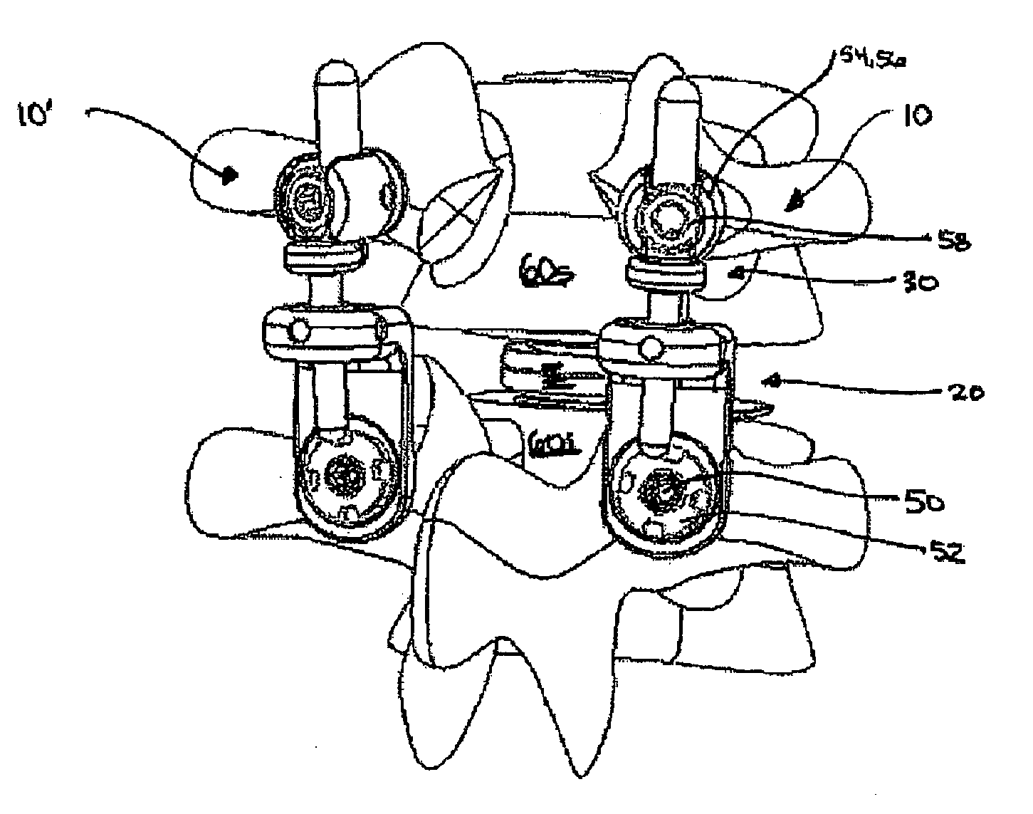
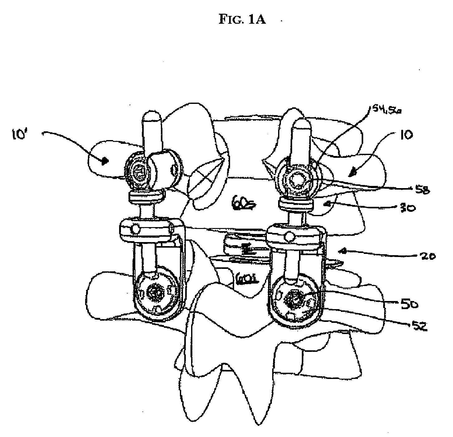
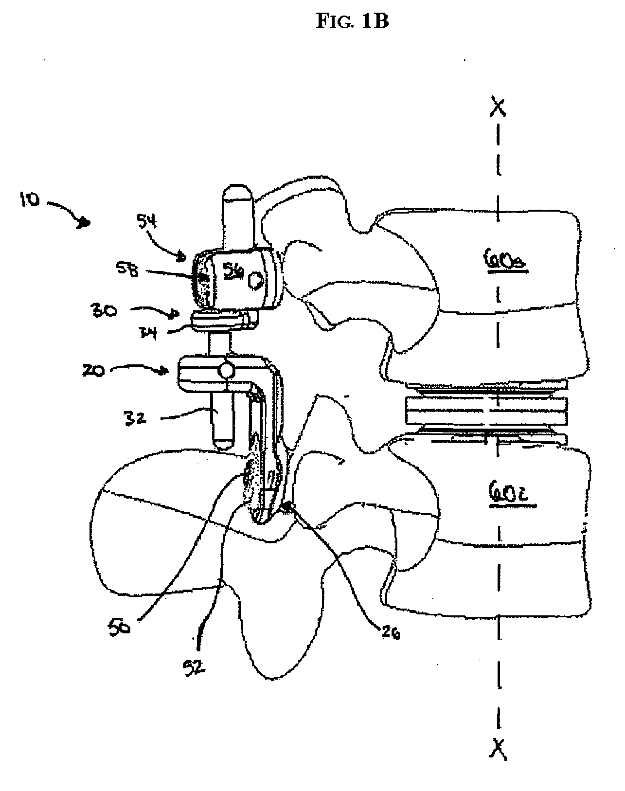
[0032] The present invention provides various methods and devices for replacing damaged, injured, diseased, or otherwise unhealthy posterior elements, such as the facet joints, the lamina, the posterior ligaments, and / or other features of a patient's spinal column. In one exemplary embodiment, the methods and devices are effective to mimic the natural function of the spine by allowing flexion, extension, and lateral bending of the spine, while substantially restricting posterior-anterior shear and rotation of the spine. A person skilled in the art will appreciate that, while the methods and devices are especially configured for use in restoring and / or replacing the facet joints and optionally other posterior elements of a patient's spine, the methods and devices can be used for a variety of other purposes in a variety of other surgical procedures.

[0033]FIGS. 1A-4C illustrate one exemplary embodiment of a posterior stabilizing implant. While two implants 10, 10′ are shown coupled to...


PUM


Abstract

Various methods and devices for replacing damaged, injured, diseased, or otherwise unhealthy posterior elements, such as the facet joints, the lamina, the posterior ligaments, and / or other features of a patient's spinal column, are provided. In one exemplary embodiment, the methods and devices are effective to mimic the natural function of the spine by allowing flexion, extension, and lateral bending of the spine, while substantially restricting posterior-anterior shear and rotation of the spine.

Description

FIELD OF THE INVENTION [0001] The present invention relates to spinal instrumentation, and in particular to various devices that are adapted to mimic the natural function of the structural posterior elements. BACKGROUND OF THE INVENTION [0002] The vertebrae in a patient's spinal column are linked to one another by the disc and the facet joints, which control movement of the vertebrae relative to one another. Each vertebra has a pair of articulating surfaces located on the left side, and a pair of articulating surfaces located on the right side, and each pair includes a superior articular surface, which faces upward, and an inferior articular surface, which faces downward. Together the superior and inferior articular surfaces of adjacent vertebra form a facet joint. Facet joints are synovial joints, which means that each joint is surrounded by a capsule of connective tissue and produces a fluid to nourish and lubricate the joint. The joint surfaces are coated with cartilage allowing ...

Claims


Application Information

Patent Timeline
Patent Type & Authority Applications(United States)
IPC IPC(8): A61F2/30
CPCA61B17/7023A61B17/7025A61B17/7031A61B17/7043A61B17/7049A61B17/7064A61F2/4405A61F2/4425A61F2002/30331A61F2002/3037A61F2002/30372A61F2002/30649A61F2002/448A61F2220/0033A61B17/70A61B17/7011A61B17/7019A61B17/7035A61B17/7046A61F2/442
Inventor KWAK, SEUNGKYU DANIELHAWKINS, JOHN RILEYBORGSTROM, AMIEDUNBAR, WILLIAM
Owner DEPUY SPINE INC (US)
Why Eureka
Try Eureka