Cervical motion preservation device

a motion preservation device and cervical spine technology, applied in the field of implantable artificial joint assemblies, can solve the problems of prohibitively complex or expensive components, adversely affecting the disc adjacent to the fused joint, imposing heightened stress and wear, etc., to achieve maximum contact area, facilitate controlled movement of adjacent vertebrae, and maximize surface contact area

Inactive Publication Date: 2011-09-13
ALTUS PARTNERS
View PDF19 Cites 2 Cited by
  • Summary
  • Abstract
  • Description
  • Claims
  • Application Information

AI Technical Summary

Benefits of technology

[0013]A preferred embodiment is directed to a three-piece, modular implant assembly that includes an upper part, a lower part, and a center core. The upper part and the lower part are identical in size and shape, though they could differ somewhat if desired or necessary. Each of the upper and the lower parts comprise a unitary body having an approximately ninety degree bend in it defining vertical and horizontal sections. The vertical section is preferably offset to one side of the vertical centerline (for reasons discussed below) and has at least one fastener hole to accommodate a fastener such as a bone screw. The hole may be slotted to allow predetermined sliding relative to a bone-screw and / or it may be shaped to allow pivoting relative to a bone-screw in instances where resultant freedom of movement of adjacent vertebrae is desired. This may be altered to a desired degree. The horizontal section has on its side facing toward the vertical section a vertebral end-face contacting surface that may be contoured and / or have projections to engage and hold securely to vertebral end faces, as well as to transfer axial load from the end faces. It may have a convex shape to it that fits and mates with the natural anatomy of the end faces to maximize surface contact area and to maximally distribute load. The side of the horizontal section facing away from the vertical section has a generally concave surface that is adapted to pivotally engage a center core of generally spherical shape. The lower part is preferably an inverted copy of the upper part so that its surfaces engage the center core and the lower adjacent vertebrae in a manner as described above with respect to the upper part. The vertical sections of each of the upper and lower parts have at least one fastener hole to enable a fastener such as a bone screw to fasten the respective part to a respective vertebra. The hole may be oversized, slotted or otherwise configured to allow relative movement of the screw and the part, thereby facilitating controlled movement of adjacent vertebrae.

Problems solved by technology

While complete fusion and, thus, resultant loss of movement between adjacent vertebrae is sometimes prescribed, fusion does limit movement and in the long term may adversely affect the disc adjacent to the fused joint by imposing heightened stress and wear.
Such shortcomings include lack of versatility so as to require multiple configurations and sizes of hardware on hand during surgery; prohibitively complex or expensive components; lack of anatomical correspondence with resultant poor fit; high stress concentrations and unnatural load forces on adjacent or fused bone segments; and other shortcomings.
Known motion preservation devices are generally restricted to only very stable constructs and degenerative disc disease cases, which is only 5%-10% of all cases.
Such designs do not provide adequate initial stability and thus are subject to, for example, lateral slide out of the insert.
In some cases this problem could be addressed by implementing additional components such as plates or artificial ligaments, thereby increasing cost, complexity, surgery time, and invasiveness.
This type of system not only causes high stress concentrations in and around the bone screws and their anchoring points in the vertebrae that are at risk for failure under load, but such a system prevents or shields axial load transfer through the end plates.
This adds to the cost or reduces the versatility of the known assemblies.
Various known assemblies require a relatively large amount of surface area of a vertebra to the extend that constructing multiple, adjacent levels of reconstructed vertebrae (i.e., spanning two or more adjacent vertebral disc spaces) is prohibited simply because there is not enough space to install all of the components required.
Such keel designs are subject to increased risk of cross-fracture of the vertebrae because they require channels to be cut which remove bone material crucial to structural integrity, and they often leave no room for additional implants such as on the opposite side of a vertebra.

Method used


Image

  • Cervical motion preservation device
  • Cervical motion preservation device
  • Cervical motion preservation device

Examples


first embodiment

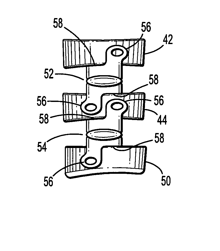
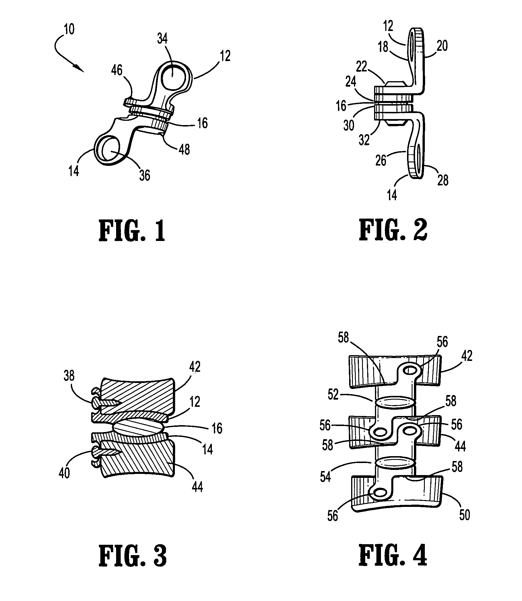
[0030]A first embodiment assembly according to the present invention is described with respect to FIGS. 1-4. An implant assembly (10) according to the present invention comprises an upper part (12), a lower part (14), and a center core (16). The upper part (12) comprises a vertical section front face (18), a vertical section rear face (20), a horizontal section top face (22), and a horizontal section bottom face (24). The lower part (14) comprises a vertical section front face (26), a vertical section rear face (28), a horizontal section top face (30), and a horizontal section bottom face (32). Each of the vertical sections of the upper part (12) and the lower part (14) comprise at least one fastener hole (34, 36). Each hole (34, 36) is adapted to receive a fastener (38, 40) such as a bone screw.

[0031]The horizontal top face (22) of the upper part (12) and the horizontal bottom face (32) of the lower part (14) are each preferably convex in shape to match the anatomical shape of the ...

second embodiment

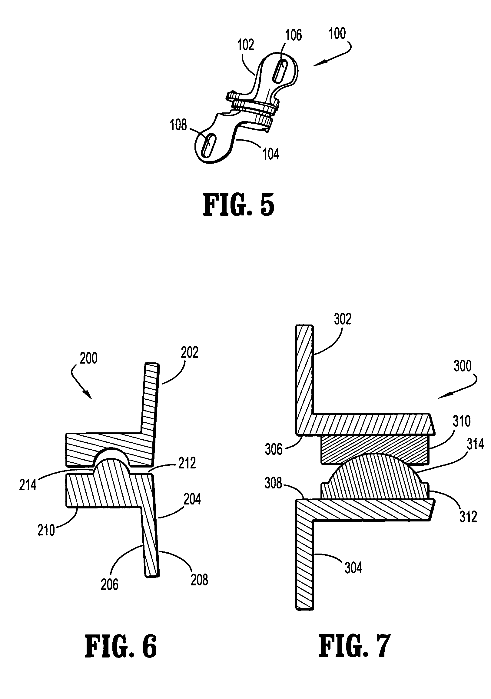
[0035]the present invention assembly (100) is shown in FIG. 5 having an upper part (102) and a lower part (104) in which respective fastener holes (106, 108) are elongated. Such elongation of the holes (106, 108) may b e used for relieving stress by allowing relative movement of the upper or lower part (102, 104) with respect to a fastener (not shown) which attaches the assembly (100) to bone structures. The elongated holes (106, 108) may also provide versatility in positioning with respect to limited fastener positions during installation. It is understood that such elongated or slotted holes (106, 108) may be provided on one or on both parts (104, 106) in any of the preferred embodiments described herein.

[0036]Another embodiment of the invention, shown in FIG. 6, is directed to an assembly (200) having an upper part (202) and a lower part (204). The upper part (202) is generally similar to the upper part (12) in the first preferred embodiment. The lower part (204) is comprised of ...


PUM


Abstract

A system of reconstruction for a spinal joint is directed to a modular implant assembly that includes an upper part and a lower part. The upper and lower parts each comprise a unitary body having an approximately ninety degree bend defining vertical and horizontal components. Each vertical component has a fastener hole for attaching it to a bone segment using a bone fastener. The horizontal sections each have a complementary contact surfaces in order to transmit compressive load therebetween and to accommodate sliding and pivoting relative movement therebetween. The vertical sections of each of the upper and lower part are offset with respect to a vertical centerline so that successive assemblies bridging more than one adjacent vertebral space can have an upper part and a lower part according to the present invention coexist on a single vertebra in a space-efficient manner wherein the vertical sections nest spatially.

Description

RELATED APPLICATIONS[0001]None.TECHNICAL FIELD[0002]The present invention relates to implantable artificial joint assemblies and, more particularly, to a joint assembly that allows a predetermined amount of desired motion to a joint and that is particularly well suited for use in restructuring a spinal disc section of a spine including, but not limited to, the cervical region.BACKGROUND OF THE INVENTION[0003]In orthopedics it is known to use various types of reconstruction assemblies to repair bone joints that have become deteriorated, damaged or degenerative, such as due to trauma or disease. Some reconstructions involve the use of various components such as bone screws, plates, bone grafts, fusion implants and other components. Depending on the type and method of reconstruction selected, complete stabilization with no movement may be selected, or a predetermined amount of controlled movement may be selected. In one technique of spinal reconstruction, for example, fusion of adjacen...

Claims


Application Information

Patent Timeline
Patent Type & Authority Patents(United States)
IPC IPC(8): A61F2/44
CPCA61F2/4425A61F2002/30578A61F2002/30649A61F2002/30662A61F2002/30777A61F2002/30841A61F2002/30884A61F2002/443A61F2002/449
Inventor KHALILI, FARID BRUCE
Owner ALTUS PARTNERS
Why Eureka
Try Eureka