Orthopedic stabilization device

a stabilization device and orthopedic technology, applied in the field of orthopedic stabilization devices, can solve the problems of not being able to resist compression or shear loads, long recovery process, and long recovery time, and achieve the effect of restoring normal range of motion and limiting the range of relative motion

Inactive Publication Date: 2006-11-23
WHITE PATRICK
View PDF99 Cites 260 Cited by
  • Summary
  • Abstract
  • Description
  • Claims
  • Application Information

AI Technical Summary

Benefits of technology

[0020] An advantage of the present invention is a device that limits the range of relative motion between two vertebral bodies and works with existing pedicle screw assemblies.
[0021] Another advantage of the invention is to provide a kit to the surgeon that has a variety of pedicle screws, rigid fusion rods and elongated implantable inelastic ligaments. Further it is desirable that the ligaments provide a variety of stiffness and flexibility options so the surgeon can select the appropriate stiffness and range of motion to achieve the desired surgical result whether it is for aiding fusion or restoring normal range of motion to a patient.
[0022] Other objects and advantages will become apparent to a reader skilled in the art, with reference to the following Figures and accompanying Detailed Description wherein textual reference characters correspond to those denoted on the Drawings.

Problems solved by technology

In attempting to fuse the patient there is a long and painful recovery process.
Most rod and screw constructs and fusion cage constructs are very rigid, not allowing transfer of stress into the fusion site that would otherwise aid in a quicker recovery.
Many are working to develop devices that allow relative motion, yet these have fallen short in preventing shear forces between the vertebral bodies being stabilized.
While the ligaments allow for relative motion, they do not appear to resist compression or shear loads, instead relying upon tension alone.
This design provides flexural degrees of freedom, allows relative motion between the vertebral bodies but does little to inhibit or prevent shearing between the vertebral bodies.
While flexibility in translation can be helpful, the spine loads in several planes at the same time and the translation spoken of in this patent would appear to inadequately redistribute stresses through the fusion site.
As a result motion is forcibly limited to one location, i.e., motion is constrained through a hinge point, which undesirably stresses the assembly construct.
The '730 design attempts to accomplish a multidirectional redistribution of force for aiding in quicker fusion rates, however its constructs were not designed for use in conjunction with a disk implant.
This constrains force through the rod in a manner causing early fatigue failure.
Further, the rod cannot be bent at the time of surgery to a preformed shape holding the vertebral bodies in a desired relative position while also limiting their relative motion.

Method used


Image

  • Orthopedic stabilization device
  • Orthopedic stabilization device
  • Orthopedic stabilization device

Examples


Embodiment Construction

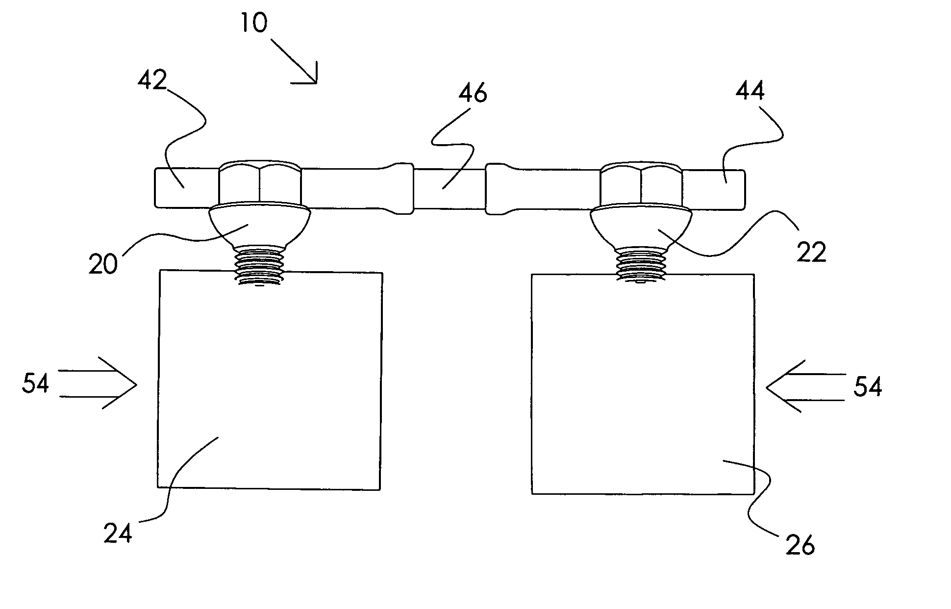
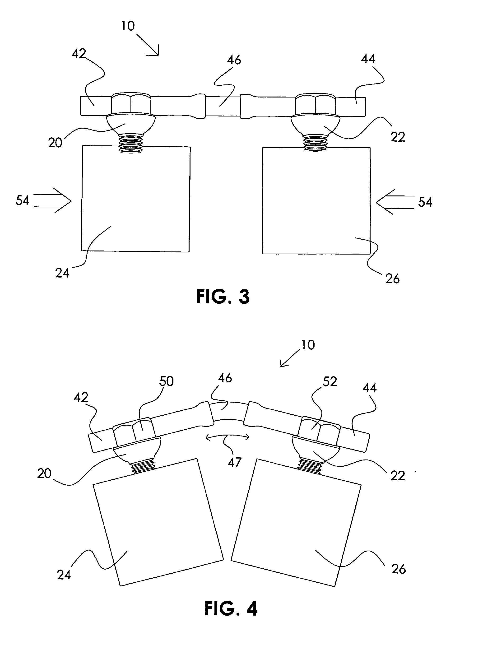
[0035] With reference generally to FIGS. 1-10, the Applicant's invention provides flexible spinal stabilization allowing controlled relative vertebral motion for the relief of pain, while preventing intervertebral shear forces. Moreover, the invention evenly distributes mechanical stresses throughout its structure rather than constraining motion within a limited portion of its structure, by virtue of its distinctive design.

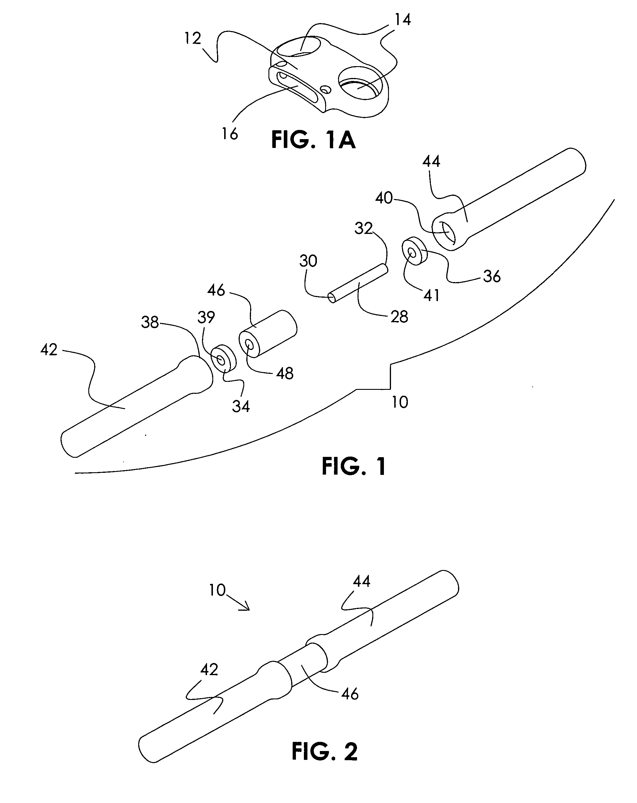
[0036] Referring to FIGS. 1 and 2-4, an elongated bridge member is generally shown as an assembly at 10. Assembly 10 includes a ligament 28 shown in the form of a wire. It will be understood that the ligament 28 may also take the form of a tube, solid rod or a band, having different cross sectional shapes and sizes. The ligament 28 is made of an implantable material selected to be inelastic at body temperature and allows relative constrained motion while resisting bodily shear forces. The ligament 28 has opposed first 30 and second 32 ends received within washer ...


PUM


Abstract

An orthopedic device is described for stabilizing the spinal column between first and second vertebral bodies. The device has first and second anchors adapted for fixation to the first and second vertebral bodies, respectively. The device further includes an elongated bridge with first and second ends operatively connected to the first and second anchors, respectively. The bridge contains an implantable ligament made preferably of a nickel titanium alloy selected to have inelastic properties at body temperature, wherein the bridge is capable of continuous plastic deformation to allow relative constrained motion between the vertebral bodies. In a preferred embodiment the device further includes a dampening member surrounding the ligament, which may be a wire, tube or band. In another preferred embodiment the device includes rigid rod members each correspondingly retained with either end of the ligament, and independently attached to the vertebral bodies with anchors. The rigid rod members are correspondingly connected to either end of the ligament. In yet another preferred embodiment, the device includes plate segments correspondingly retained with either end of the ligament, and independently attached to the vertebral bodies with a plurality of anchors. Other preferred devices and kits containing such devices are also described.

Description

RELATED APPLICATION [0001] This application claims priority from U.S. Provisional Application No. 60 / 677,699, filed May 4, 2005 by the present inventor.BACKGROUND OF THE INVENTION [0002] 1. Technical Field of the Invention [0003] The present invention relates to orthopedic stabilization devices used to limit the relative motion of at least two vertebral bodies for the relief of pain. These devices can be used to aid osteo-synthesis in combination with fusion devices, supplement other motion restoring devices such as disk implants or used solely to restrict the motion of vertebral bodies without other devices. [0004] 2. Description of the Related Art [0005] In the field of spine surgery there have been many attempts to relieve pain associated with spinal injury or illness. Traditionally surgeons have fused the vertebral bodies with a pedicle screw and rod construct or a fusion cage. In attempting to fuse the patient there is a long and painful recovery process. Most rod and screw con...

Claims


Application Information

Patent Timeline
Patent Type & Authority Applications(United States)
IPC IPC(8): A61F2/30
CPCA61B17/7004A61B2017/00867A61B17/7031
Inventor WHITE, PATRICK M.
Owner WHITE PATRICK
Why Eureka
Try Eureka