Prosthetic facet joint ligament

a facet joint and prosthesis technology, applied in the field of prosthetic facet joint ligaments, can solve problems such as not fully restoring joint functionality, and achieve the effects of stabilizing the facet joint, preventing the proliferation of debris, and relieving pain

Inactive Publication Date: 2006-09-05
DEPUY SPINE INC (US)
View PDF20 Cites 258 Cited by
  • Summary
  • Abstract
  • Description
  • Claims
  • Application Information

AI Technical Summary

Benefits of technology

[0017]Replacing the articular surface may relieve pain, but does not fully restore joint functionality.
[0018]Accordingly, the present inventors recognized a ne

Problems solved by technology

Replacing the articular surface may relieve pain

Method used


Image

  • Prosthetic facet joint ligament
  • Prosthetic facet joint ligament
  • Prosthetic facet joint ligament

Examples


first embodiment

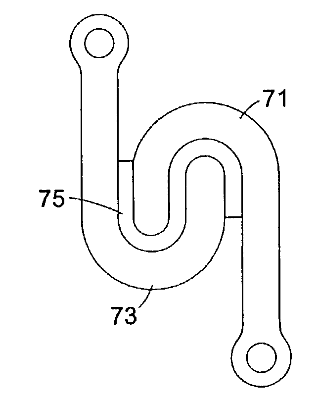
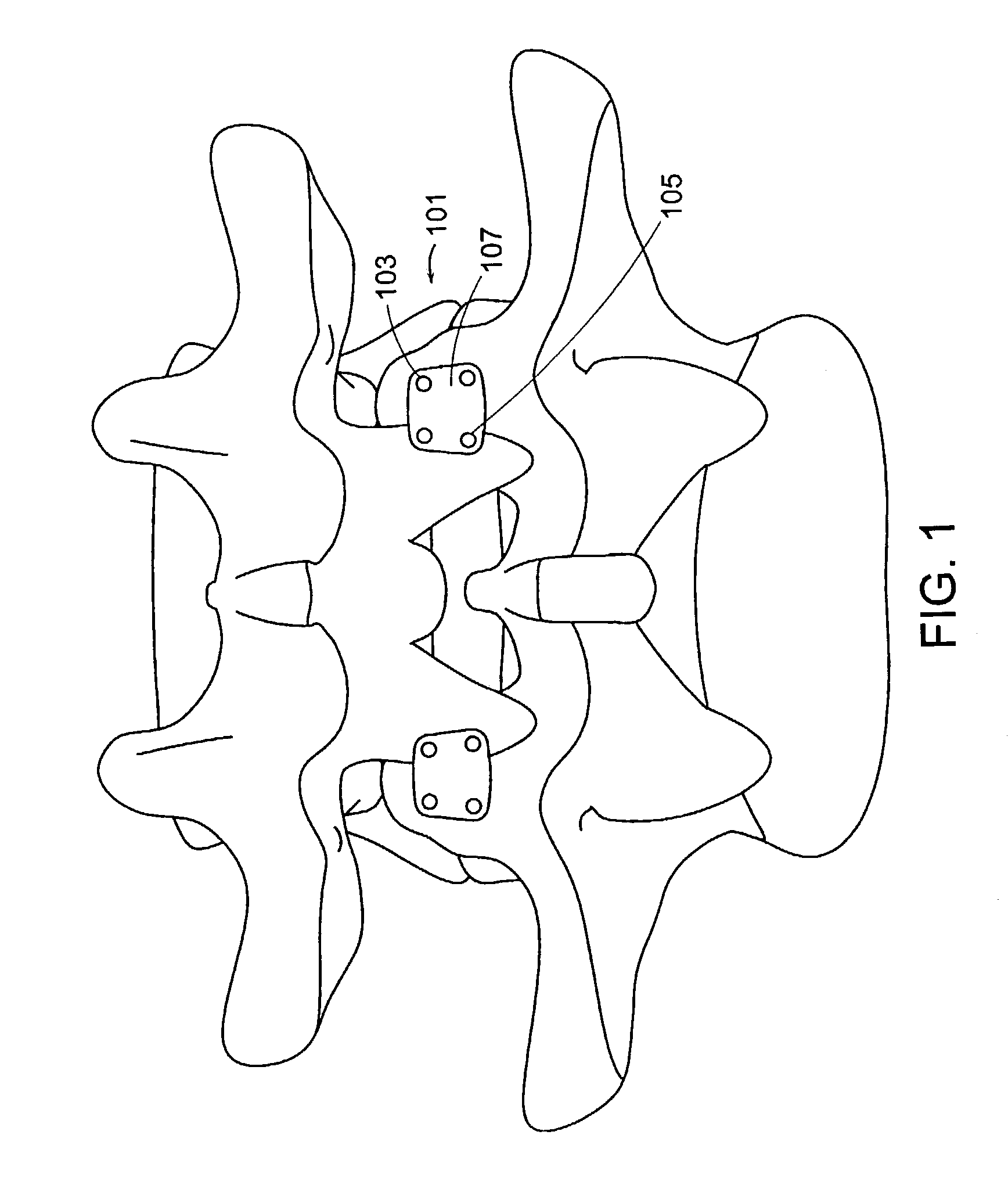
[0046]Now referring to FIG. 1, there is provided the facet joint ligament 101 of the present invention. The ligament comprises first 103 and second 105 attachment end portions and an intermediate portion 107. The first attachment end portions attaches to the superior facet SF of the facet joint, while the second attachment end portion attaches to the inferior facet IF of the facet joint. Thus, the ligament traverses the facet joint.

second embodiment

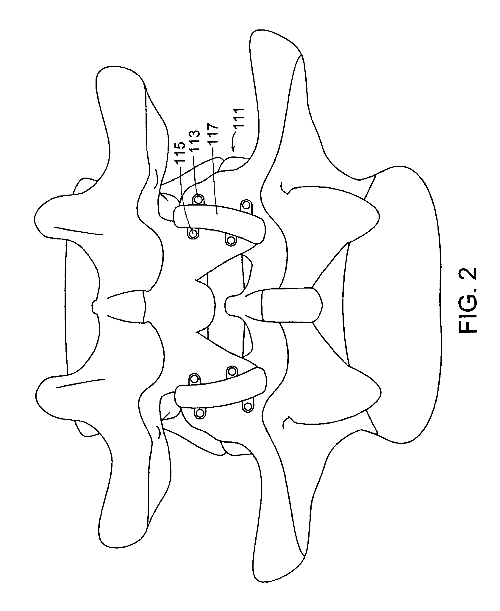
[0047]Now referring to FIG. 2, there is provided the facet joint ligament of the present invention, wherein the ligament is a capsule 111 surrounding the facet joint The capsule comprises first 113 and second 115 attachment end portions and a sheath portion 117. The first attachment end portions attaches to the superior facet SF of the facet joint, while the second attachment end portion attaches to the inferior facet IF of the facet joint. The sheath traverses and completely circumscribes the facet joint. In this FIG. 2, the sheath may cover a portion of the exposed bony surface.

[0048]The ligament of the present invention can be made of any biocompatible material adapted for constraining but not totally eliminating relative movement between facet joints. In this regard, the facet joint ligament of the present invention mimics the natural facet joint capsule. The ligament of the present invention comprises three features. First it must be adapted to traverse a facet joint. Second, i...


PUM

PropertyMeasurementUnit
Elasticityaaaaaaaaaa

Abstract

This invention relates to a spinal facet joint ligament.

Description

BACKGROUND OF THE INVENTION[0001]One of the most common surgical interventions today is arthrodesis, or spine fusion, in which two or more adjacent vertebral bodies are fused together in order to alleviate pain associated with the disc(s) located between those vertebral bodies. Approximately 300,000 such procedures are performed annually in the United States alone. Clinical success varies considerably, depending upon technique and indications, and consideration must be given to the concomitant risks and complications.[0002]While spine fusion generally helps to eliminate certain types of pain, it has also been shown to decrease function by limiting the range of motion for patients in flexion, extension, rotation and lateral bending. Furthermore, it is believed that spine fusion creates increased stresses on (and, therefore, accelerated degeneration of) adjacent non-fused motion segments. Additionally, pseudoarthrosis, resulting from an incomplete or ineffective fusion, may reduce or ...

Claims


Application Information

Patent Timeline
IPC IPC(8): A61F2/08A61B17/08A61B17/04A61B17/70A61F2/00A61F2/02A61F2/30A61F2/44
CPCA61F2/08A61F2/30A61F2/4405A61B17/0401A61F2310/00976A61B17/7064A61F2/30742A61F2/30965A61F2/442A61F2/4425A61F2/4455A61F2002/30014A61F2002/30032A61F2002/30062A61F2002/30224A61F2002/30242A61F2002/30383A61F2002/30462A61F2002/30507A61F2002/30553A61F2002/30563A61F2002/30565A61F2002/30578A61F2002/30649A61F2002/30662A61F2002/30673A61F2002/30682A61F2002/30772A61F2002/30774A61F2002/30777A61F2002/30841A61F2002/443A61F2210/0004A61F2220/0025A61F2220/0075A61F2230/0069A61F2230/0071A61F2250/0008A61F2250/0018A61F2250/003A61F2310/00011A61F2310/00017A61F2310/00023A61F2310/00029A61F2310/00161A61F2310/00179A61F2310/00365A61F2310/00796A61B17/7011
Inventor DOORIS, ANDREWSERHAN, HASSAN A.GRACIA, MARK
Owner DEPUY SPINE INC (US)
Why Eureka
Try Eureka