Intracranial Red Light Treatment Device For Chronic Pain

a technology treatment device, which is applied in the field of intracranial red light treatment device for chronic pain, can solve the problems of failure, low back pain, and a significant proportion of patients who undergo this surgery and yet still experience chronic back pain, and achieve the effect of stimulating the release of pain-reducing endorphins and increasing the beta-endorphin plasma concentration in those patients

Inactive Publication Date: 2010-08-05
DEPUY SYNTHES PROD INC
View PDF101 Cites 46 Cited by
  • Summary
  • Abstract
  • Description
  • Claims
  • Application Information

AI Technical Summary

Benefits of technology

[0005]It has been reported in the literature that low level irradiation of tissue with red light stimulates the release of pain-reducing endorphins from the irradiated cells. For example, Laakso, Photomed Laser Surg. February 2005;23(1):32-5 induced inflammation in the hind-paws of Wistar rats. Two groups of rats then received 780-nm laser therapy at one of two doses (2.5 J / cm2 and 1 J / cm2). Scores of nociceptive threshold were recorded using paw pressure and paw thermal threshold measures. Laakso found that a dose of 2.5 J / cm2 provided a statistically significant effect on paw pressure threshold (p<0.029) compared to controls. Laakso further found normal beta-endorphin containing lymphocytes in control inflamed paws but no beta-endorphin containing lymphocytes in rats that received laser at 2.5 J / cm2. Without wishing to be tied to a theory, it is believed that these results appear to show the release of endorphins from the lymphocytes of the irradiated rats. Lastly, Zalewska-Kaszubska, Lasers Med Sci. 2004;19(2):100-4, reported treating patients with 20 consecutive daily helium-neon laser neck biostimulations and 10 auricular acupuncture treatments with argon laser (every 2nd day), and finding that the beta-endorphin plasma concentration in those patients was increased.

Problems solved by technology

The leading cause of lower back pain arises from rupture or degeneration of lumbar intervertebral discs.
Although the use of fusion devices to treat back pain has become increasingly popular, there remains a significant proportion of patients who undergo this surgery and yet still experience chronic back pain.
Although DBS has had some success as a medical implant, this mode of treatment also has some drawbacks.
For example, it appears that scar tissue forms around the electrodes, causing their failure in many cases after about two years.
In addition, Since the patient's anatomy controls the flow of electrical current, it is difficult to control the location and dose of the current.
Moreover, it is believed that electricity jolts or provokes cellular response,rather than enabling or eliciting response.

Method used


Image

  • Intracranial Red Light Treatment Device For Chronic Pain
  • Intracranial Red Light Treatment Device For Chronic Pain
  • Intracranial Red Light Treatment Device For Chronic Pain

Examples


Embodiment Construction

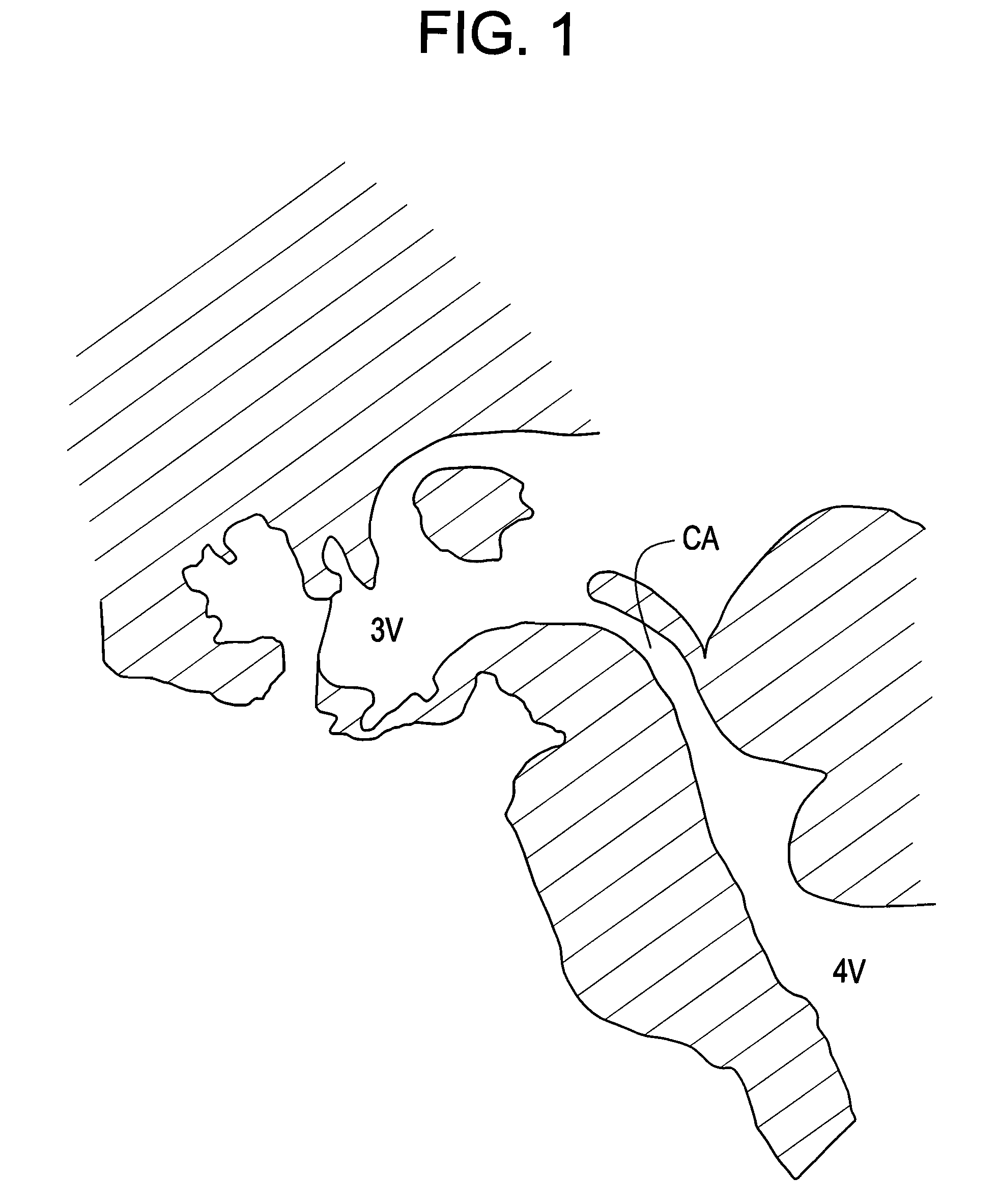
[0029]Now referring to FIG. 1, there is provided a cross-section of the brain in which the cerebral aqueduct CA connects the third ventricle 3V with the fourth ventricle 4V.

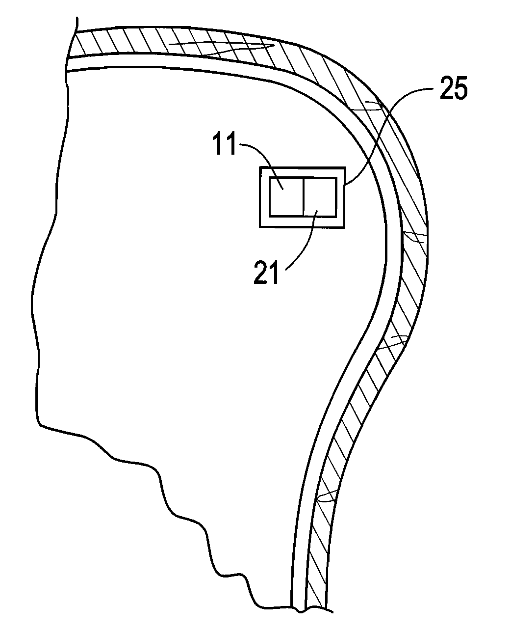
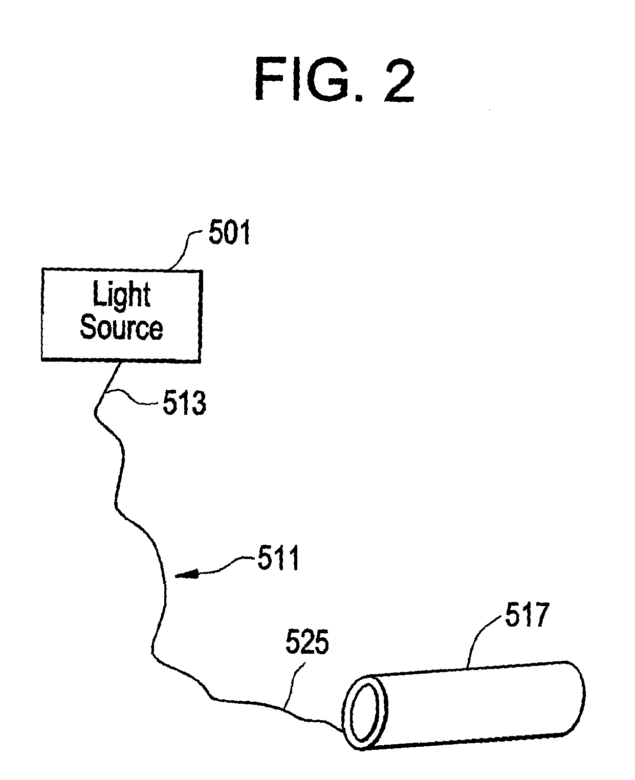
[0030]In one preferred embodiment of the present invention, the distal end of the optical wave guide is attached to a translucent light diffuser, which is often in the form of a tube. The light diffuser is placed in the cerebral aqueduct and acts not only as a light delivery device to the PAG (which surrounds the cerebral aqueduct), but also as an anchor within the compliant cerebral aqueduct that holds the device in place.

[0031]The literature has repeatedly reported the successful placement of stents in the cerebral aqueduct as a method of managing blockage of the cerebral aqueduct or fourth ventricle. See, for example, Shin, J. Neurosurg., June 2000 92(6) 1036-9; Cinalli, J. Neurosurg., January 2006, 104(1 Supp.) 21-7; Sagan, J. Neurosurg. (4 Supp pediatrics) 105: 275-280, 2006; Schroeder, Operative Neurosurger...


PUM


Abstract

Placement of a silicone tube in the cerebral aqueduct and the transmission of red light through it, resulting in the irradiation and consequent biostimulation of the adjacent periaqueductal gray, thereby causing the release of endorphins therefrom and pain relief.

Description

BACKGROUND OF THE INVENTION[0001]The leading cause of lower back pain arises from rupture or degeneration of lumbar intervertebral discs. Pain in the lower extremities is caused by the compression of spinal nerve roots by a bulging disc, while lower back pain is caused by collapse of the disc and by the adverse effects of articulation weight through a damaged, unstable vertebral joint. One proposed method of managing these problems is to remove the problematic disc and replace it with a porous device that restores disc height and allows for bone growth therethrough for the fusion of the adjacent vertebrae. These devices are commonly called “fusion devices”. Although the use of fusion devices to treat back pain has become increasingly popular, there remains a significant proportion of patients who undergo this surgery and yet still experience chronic back pain. This phenomenon is called “failed back syndrome”.[0002]Deep Brain Stimulators (DBS) have been used to treat chronic pain, in...

Claims


Application Information

Patent Timeline
Patent Type & Authority Applications(United States)
IPC IPC(8): A61N5/06
CPCA61N1/3787A61N5/0601A61N2005/0659A61N2005/0651A61N2005/063
Inventor TOSELLI, RICHARDDIMAURO, THOMAS M.FISHER, MICHAEL A.LILIENFELD, SEAN
Owner DEPUY SYNTHES PROD INC
Why Eureka
Try Eureka