Treatment of pain

US20050055065A1Inactive Publication Date: 2005-03-10ARC 1

Image

  • Treatment of pain
  • Treatment of pain
  • Treatment of pain

Examples


Embodiment Construction

[0015] I. Devices

[0016] A. Electrodes

[0017] Electrodes can be obtained from a variety of commercial sources. These are typically characterized by small size and flexibility.

[0018] Flexible electrodes are described by U.S. Pat. Nos. 6,024,702 and 5,012,810 incorporated by reference herein. Flexible conductive materials can also be used in making the electrodes as described in U.S. Pat. No. 6,495, 020. For example, an electrode member can comprise a strip of material having a thickness of about 10-20 micrometers, such as IMPERIAL® lapping film No. 15 MIC LF S / C (3M Co® , St. Paul, Minn.), having a coating of silver / silver chloride of about 0.3-0.7, and preferably about 0.5, micrometers thick thereon.

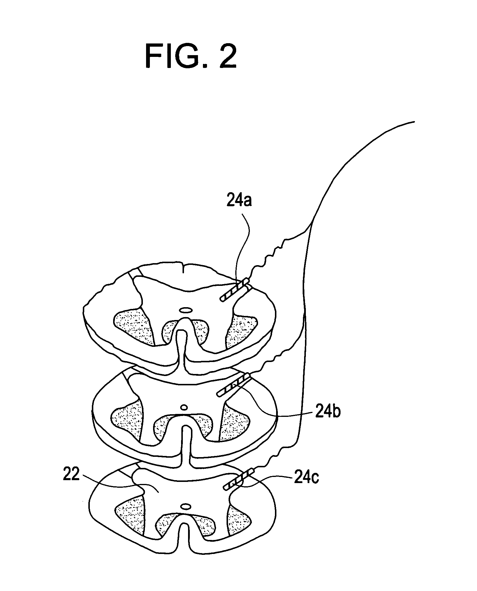
[0019] The electrodes must be small enough to be implanted into the dorsal horn and other areas of the spinal cord. One such device is, for example, the MEDTRONIC® S Model 3387 quadripolar lead, which has been approved by the FDA for several years for unilateral deep brain stimulation ...


PUM


Abstract

The method disclosed herein entails spinal cord stimulation via electrodes placed directly into the spinal cord. Electrodes are placed directly into the dorsal horn, dorsal column, spinothalamic tract, nucleus cuneatus, nucleus gracilis, spinal tract of V, or spinal nucleus of V (nucleus caudalis) depending on the source of pain. This “intramedullary” stimulation “jams” or otherwise prevents the pain signal from being transmitted. The placement of the electrodes is accomplished through an open surgical procedure in which the dura is opened to allow the surgeon direct access to the spinal cord. In the case of SCI (or disease), the electrodes are positioned in the dorsal horn of the spinal cord within several dermatomal segments of the lesion site. Stimulation with intramedullary electrodes can be used to treat other types of pain where stable stimulation of the dorsal columns (and the analogous structures for the face), or their nuclear counterparts (nucleus cuneatus, nucleus gracilis, nucleus caudalis) should relieve pain. Stimulation of the spinothalamic tract may also be achieved by intramedullary placement of electrodes. The method provides a means to stimulate the targeted area directly, creating a stable means of stimulating the desired area, and decreasing stimulation of other structures.

Description

CROSS-REFERENCE TO RELATED APPLICATIONS [0001] This application claims priority to U.S. Ser. No. 60 / 488,857 filed Jul. 18, 2003.FIELD OF THE INVENTION [0002] This invention is generally in the field of compositions and methods for electrically stimulating the dorsal horn and other regions of the spinal cord to interfere with or otherwise block transmission of neural signals concerned with pain. The technique involves placement of electrodes directly into the spinal cord in order to activate selectively the target region. This technique improves delivery of electrical stimuli to the desired portion of the spinal cord and serves to decrease power requirements. BACKGROUND OF THE INVENTION [0003] Spinal Cord Injury. [0004] Pain resulting from trauma or other diseases of the nervous system is termed neuropathic pain. The abnormal pain includes ongoing (spontaneous or stimulus independent pain) and heightened pain to stimuli (hyperalgesia). Spinal cord injury (SCI), one cause of neuropath...

Claims


Application Information

Patent Timeline
10 Mar 2005
Publication
US20050055065A1
IPC
A61N1/05; A61N1/18; A61N1/34
CPC
A61N1/36071; A61N1/0551
Inventors
CAMPBELL, JAMES N.