
Folding filter frame and filter

a filter frame and filter technology, applied in the field of filter frame and filter, can solve the problems of large space needed, inconvenient or difficult use, inconvenient reassembling prior to use, etc., and achieve the effect of reducing the shipping volume of the filter, convenient and fast deployment, and convenient us

Inactive Publication Date: 2008-02-14
RPS PRODS
View PDF19 Cites 30 Cited by
  • Summary
  • Abstract
  • Description
  • Claims
  • Application Information

AI Technical Summary

Benefits of technology

"The present system is a folding filter frame and filter that meets or exceeds the needs of economical, fast, and easy-to-deploy filters. The frame is made up of at least two end assemblies, each with a center stationary panel and folding panels that can be folded onto the ends of the stationary panel. The folding panels have a folding end and a free end. The folding end is securely attached to the stationary panel. There is at least one stationary support that connects the two end assemblies. The filter frame can be easily unfolded and guided from a folded configuration to a deployed configuration by moving the engagement devices in the tracks. The filter frame is used in a filter that reduces shipping volume by more than half and does not require tools for redeployment. The consumer only needs to unfold the panels and slide them outward along a track. An optional lock holds the filter in the deployed configuration during use."

Problems solved by technology

Even though they are only a few inches thick, a large amount of space is needed to package, ship, warehouse, store and display the filters as they move from the manufacturing facility to the consumers' hands.
Although the filter cabinet does collapse, the manner in which it does so makes it inconvenient to reassemble prior to use.
Although collapsible filter frames and filters are known, they can be inconvenient or difficult to use.
A consumer purchasing a furnace filter is unlikely to spend time reassembling a filter or getting out tools needed to put it together.

Method used


Image

  • Folding filter frame and filter
  • Folding filter frame and filter
  • Folding filter frame and filter

Examples


Embodiment Construction

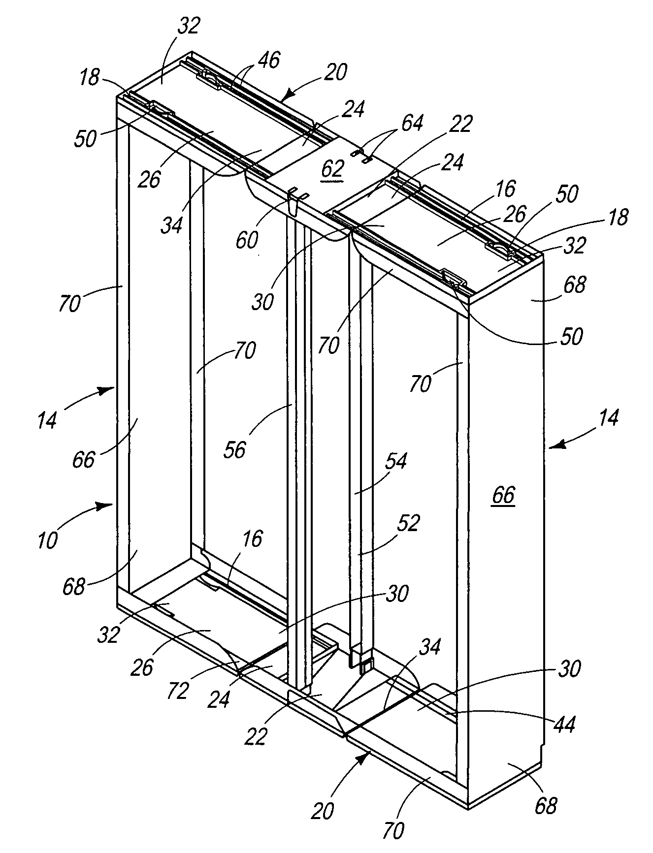
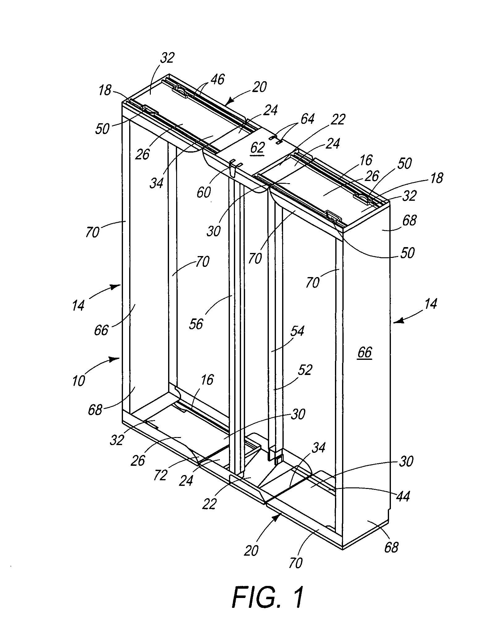
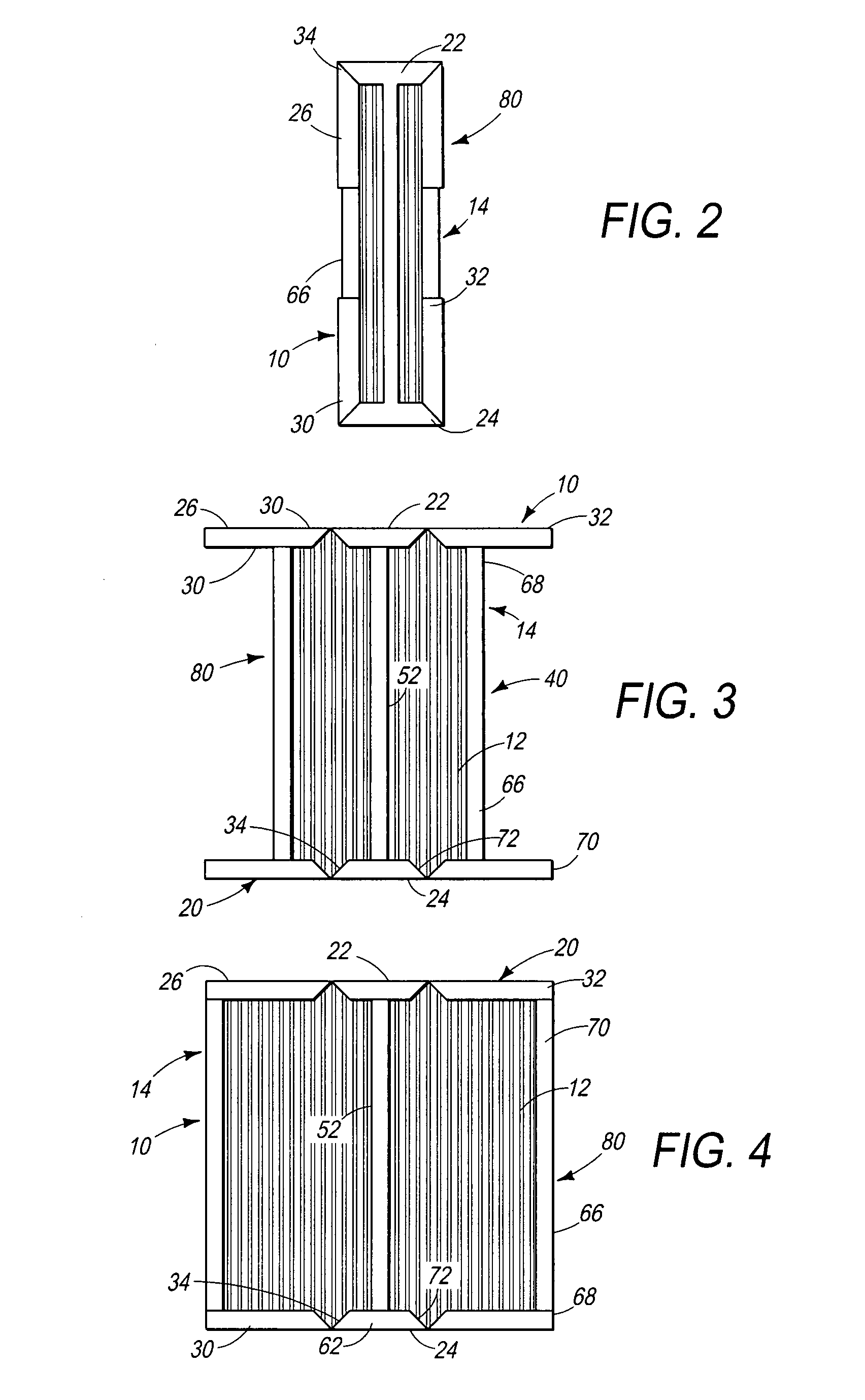
[0014]Referring to FIGS. 1-4, a folding filter frame, generally 10, is made to compactly house a filter media 12 during packaging, shipping and storage, but it opens to form a full-sized filter prior to use. For example, a 20 inch by 25 inch furnace opening may be only 6 inches by 20 inches when purchased because the filter media 12 frame is in a folded configuration. Prior to use, the filter media 12 is unfolded to the deployed configuration when it will attain the full 20 inch by 25 inch size. The frame 10 holds the filter media 12 in place to filter the furnace air.

[0015]Designations as to the top, bottom and sides of this filter frame 10 are completely arbitrary. For the purposes of making and using this filter frame 10, orientation of the frame makes no difference. For purposes of this discussion, any directional references refer to the filter frame 10 as it is oriented in FIG. 1, however, it is to be understood that these references are for ease of discussion only and are not ...


PUM

PropertyMeasurementUnit
sizeaaaaaaaaaa
sizeaaaaaaaaaa
lengthaaaaaaaaaa

Abstract

A folding filter frame includes two end assemblies, each having a stationary panel having two ends, two folding panels, each having a folding end and a free end, and at least one track. The folding end of each folding panels is foldably secured to one of the ends of the stationary panel and the track runs perpendicular to a length of the end assembly. There is a stationary support extending from one end assembly to the other end assembly. Two side assemblies are present, each including a side panel with two ends and a engagement device secured to each end. The engagement device follows one the tracks of the end panels. The filter frame converts from a folded configuration to a deployed configuration by unfolding the folding panels and sliding the engagement devices in the tracks. A filter is made by positioning a filter media inside the folding frame.

Description

FIELD OF THE INVENTION[0001]This invention relates to a filter and filter frame. More specifically, it relates to a filter frame that has a folded configuration for storage and shipping, and a deployed configuration for use in a furnace or air purifier.BACKGROUND[0002]To perform satisfactorily, an air filter spreads a filter media over a surface area through which air passes. As the surface area increases, it becomes easier for the air to pass through the filter without requiring a high-powered fan to promote air circulation. However, as the surface area of the filter media increases, the frame usually increases in size to support the filter media over the larger surface area.[0003]A typical disposable furnace filter can run as large as twenty inches square, twenty by twenty-five inches or even larger. Even though they are only a few inches thick, a large amount of space is needed to package, ship, warehouse, store and display the filters as they move from the manufacturing facility...

Claims


Application Information

Patent Timeline
Patent Type & Authority Applications(United States)
IPC IPC(8): B01D46/00
CPCB01D46/521B01D46/0005Y10S55/31
Inventor SCHULD, DANIEL E.JURSICH, DONALD N.HOPMAN, EDWARD M.SQUIER, ROBERT C.
Owner RPS PRODS
Learn More