Disk apparatus

a technology of a disk and a head is applied in the field of disk devices, which can solve the problems of css type being disadvantageous for impact, more likely to occur, and troublesome adsorption of magnetic disks, so as to reduce the possibility of contact with the head, stabilize the environment of the head, and suppress the disturbance of airflow

Inactive Publication Date: 2008-02-14
TOSHIBA STORAGE DEVICE CORP
View PDF5 Cites 7 Cited by
  • Summary
  • Abstract
  • Description
  • Claims
  • Application Information

AI Technical Summary

Benefits of technology

[0042]Since a disk rotates, the airflow control plate cannot be brought into contact with the disk. Hence, the side surface of the airflow control plate is opposed to the side surface of the disk, the airflow control plate extends while having the constant gap between the airflow control plate and the side surface of the disk. With this, it is possible to suppress the disturbance of the airflo...

Problems solved by technology

Thus, stiction troubles that the magnetic disk is adsorbed as it is if the magnetic head once comes into contact with the magnetic disk surface are more likely to occur.
In the case of the CSS type, since the magnetic head comes into contact with the mag...

Method used


Image

  • Disk apparatus
  • Disk apparatus
  • Disk apparatus

Examples


first embodiment

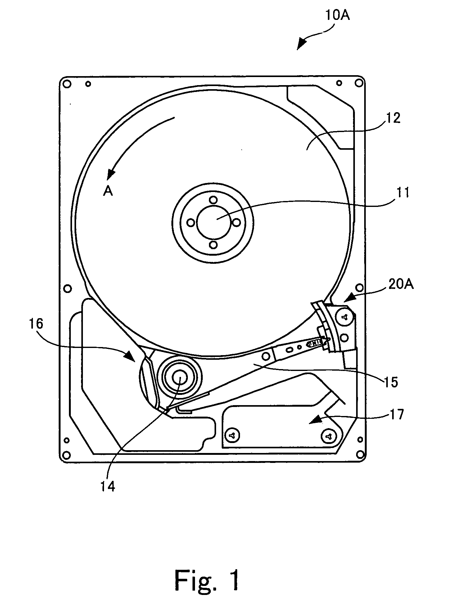
[0057]FIG. 5 is a schematic plan view showing a state of a load / unload type magnetic disk apparatus of the present invention from which an upper cover is detached.

[0058]A magnetic disk apparatus 10B shown in FIG. 5 is different from the magnetic disk apparatus shown in FIG. 1 only in shape of the ramp. Therefore, common elements are shown with the same symbols as those in FIG. 1, and redundant explanation will be omitted.

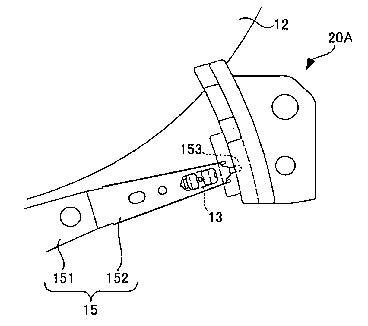
[0059]FIG. 6 is an enlarged plan view of a ramp 20B and a tip end of an arm 15 of the magnetic disk apparatus 10B shown in FIG. 5. FIG. 7 is a perspective view of the ramp 20B.

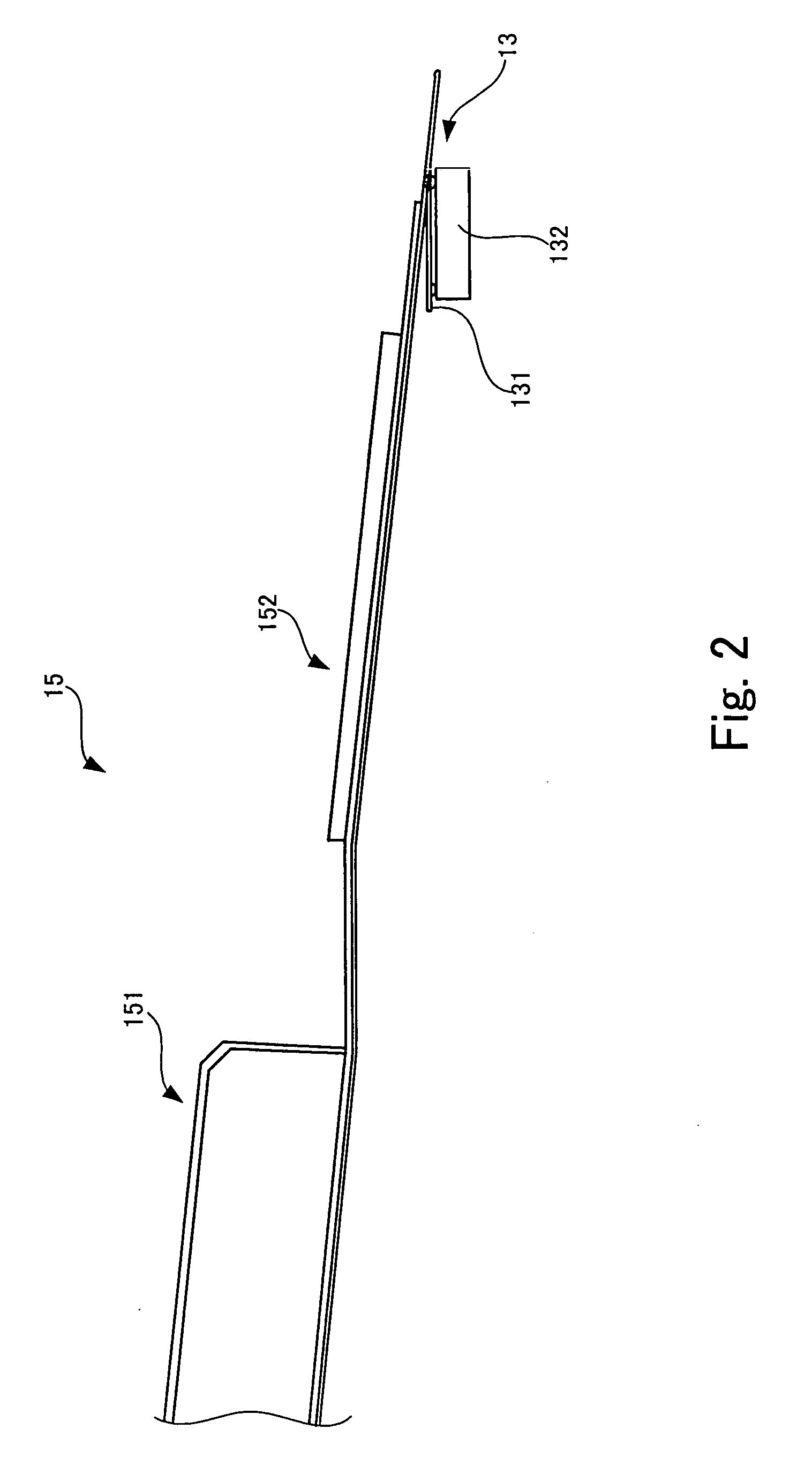
[0060]As compared with the magnetic disk apparatus 10A explained with reference to FIGS. 1 to 4, the structure of the arm (see FIG. 2) is the same, and the structure of the ramp is different.

[0061]The ramp 20B of the magnetic disk apparatus 10B of this embodiment includes an airflow control plate 22 widening from a tongue 21 toward a rotation shaft 14 of the arm 15 (see FIG. 5) as shown in FIG...

second embodiment

[0067]FIG. 9 is a schematic diagram showing a state of a magnetic disk apparatus of the present invention from which an upper cover is detached.

[0068]Elements having the same functions as those of the magnetic disk apparatuses 10A and 10B shown in FIGS. 1 and 5 are designated with the same symbols as those shown in FIG. 1 even through shapes thereof are different. Only essential different points will be explained.

[0069]In a magnetic disk apparatus 10C shown in FIG. 9, four magnetic disks 12 having the same shapes are coaxially superposed on one another at predetermined distances from one another. The magnetic disks 12 are rotated simultaneously in the direction of arrow A. Correspondingly, the same number of arms 15 as that of the magnetic heads which access first surfaces and second surfaces of the four magnetic disks 12 are formed, and the arms 15 are turned simultaneously.

[0070]A magnetic disk apparatus 10 includes a ramp 20C for holding a tip end of each arm 15 at the time of un...


PUM


Abstract

A disk apparatus includes a ramp which holds a tip end of an arm at a position away from a disk, and a slit shroud having an airflow control plate. A side surface of the airflow control plate is opposed to a side surface of the disk, the airflow control plate spreads to a position where the airflow control plate is superposed on the tip end of the arm held by the ramp. The airflow control plate has the same thickness as that of the disk, and is flush with the disk 12.

Description

BACKGROUND OF THE INVENTION[0001]1. Field of the Invention[0002]The present invention relates to a disk apparatus which positions a head above a rotating disk and which accesses the disk.[0003]2. Description of Related Art[0004]Conventionally, magnetic disk apparatuses are provided in computers externally or internally and in recent years, the magnetic disk apparatuses are incorporated not only in computers, but also in video cassette recorders, digital cameras, car navigation systems and the like.[0005]The magnetic disk apparatuses are roughly divided into a type called CSS (contact stop start) type, and a type called load / unload type. According to the CSS type, a magnetic head which accesses a magnetic disk is left on the magnetic disk. In the case of this CSS type, if the magnetic disk rotates, the magnetic head slightly floats up from the magnetic disk surface by airflow caused by the rotation, and the magnetic head accesses the magnetic disk in this state.[0006]On the other han...

Claims


Application Information

Patent Timeline
IPC IPC(8): G11B5/54
CPCG11B21/22G11B5/54
Inventor MATSUDA, YOSHIHARUKANEKO, HISASHISUWA, MASAYAWATANABE, TORUKIDO, TAKUMASUZUKI, YASUO
Owner TOSHIBA STORAGE DEVICE CORP
Why Eureka
Try Eureka