Indwelling catheter, hollow needle, and indwelling needle assembly

a technology of indwelling catheter and hollow needle, which is applied in the direction of guide needles, catheters, injection needles, etc., can solve the problems of difficult securing of sufficient flow amount for medical interventions, sharp pricking pain, etc., and achieve sufficient flow amount and relive the pain of insertion

Inactive Publication Date: 2008-02-14
MEDIKIT CO LTD
View PDF15 Cites 116 Cited by
  • Summary
  • Abstract
  • Description
  • Claims
  • Application Information

AI Technical Summary

Benefits of technology

[0008]The present invention is intended for providing an indwelling catheter, a hollow needle, and an indwelling needle assembly which can be relive a pain of insertion by making the inserted portion thin and can secure a sufficient flow amount for the medical interventions.

Problems solved by technology

However, with the above-mentioned indwelling needle, a person who is inserted the indwelling needle (hereinafter, he / she is called “patient”) may feel a sharp pricking pain when the indwelling needle is inserted, because the inserted portions of the inner needle and the catheter is thick.
But it results in that securing of a sufficient flow amount for the medical interventions becomes hard.

Method used


Image

  • Indwelling catheter, hollow needle, and indwelling needle assembly
  • Indwelling catheter, hollow needle, and indwelling needle assembly
  • Indwelling catheter, hollow needle, and indwelling needle assembly

Examples


first embodiment

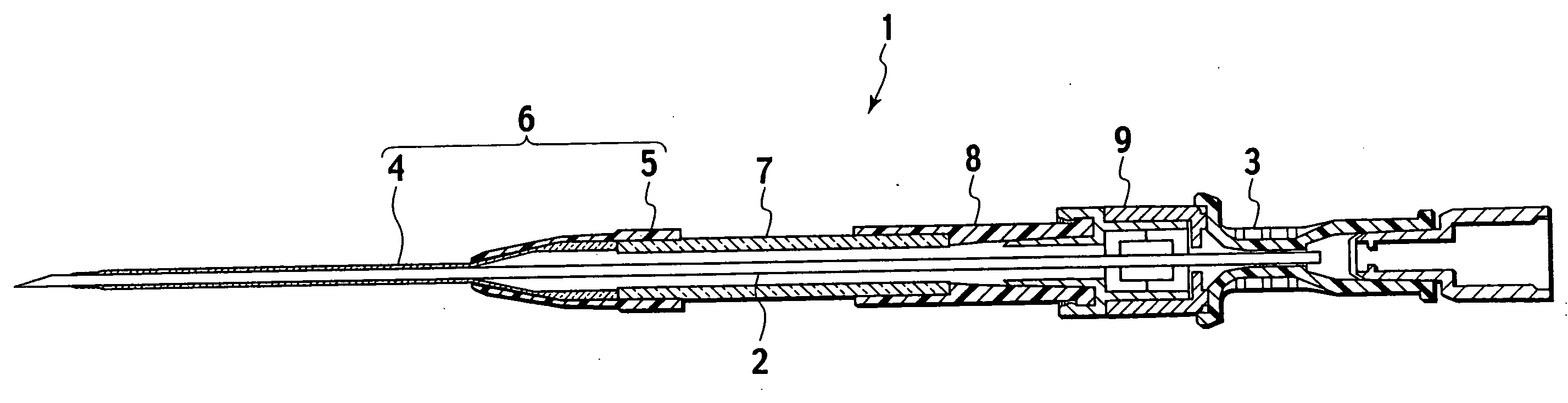
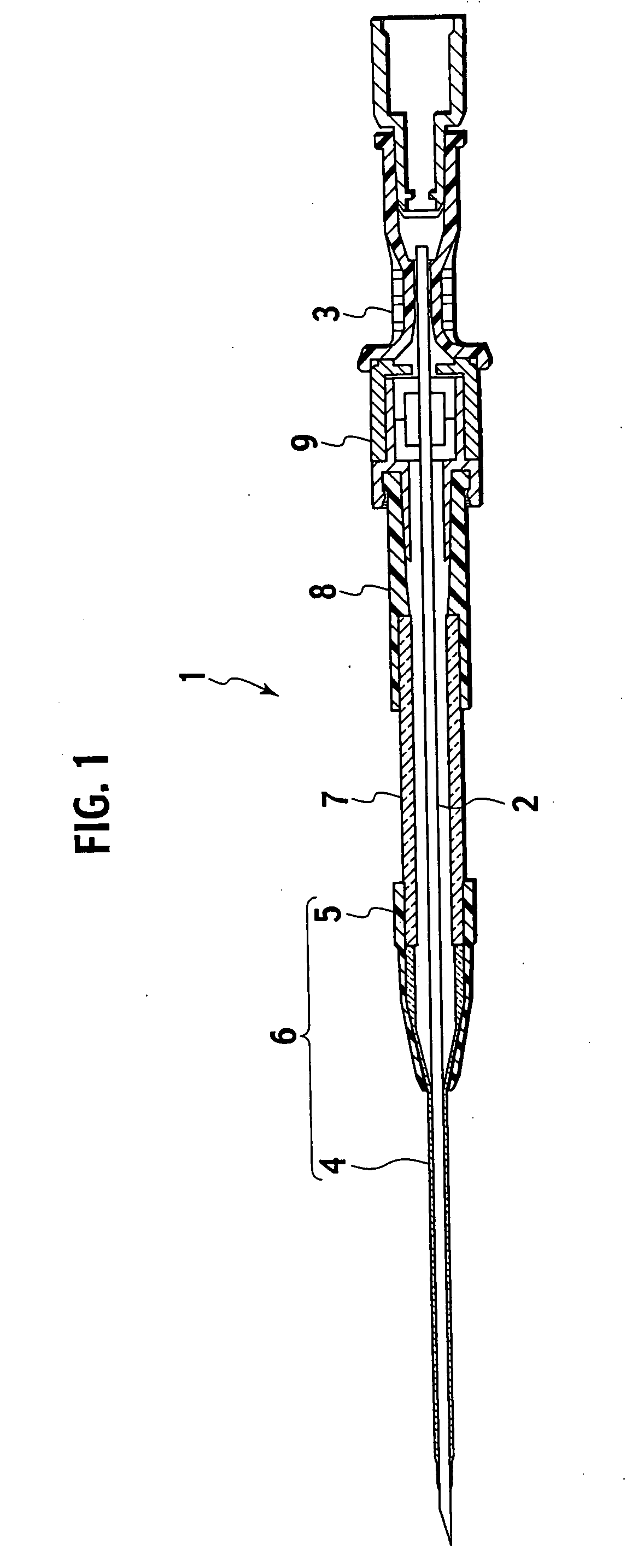
[0032]A first embodiment of the present invention will be described hereinafter with reference to drawings. FIG. 1 is a cross sectional view showing a structure of an indwelling needle assembly 1 having an indwelling catheter 6 according to the first embodiment.

[0033]As shown in FIG. 1, the indwelling needle assembly 1 is provided with an inner needle (hollow needle) 2 which is to be inserted into a patient, an inner needle base 3 holding a base end of the inner needle 2, a catheter 6 provided with a catheter tube 4 and a catheter base 5, a clamp tube 7 connected to the catheter 6, a connector (luer connector) 8, and a hemostatic valve 9.

[0034]The inner needle 2 is a hollow needle which is inserted into a lumen of a catheter tube 4. The inner needle 2 has an outer diameter which is slightly smaller than an inner diameter of the catheter tube 4 to be able to be inserted thereinto. The inner needle 2 is made of stainless steel, aluminum, titanium, composition metal of these metal mate...

second embodiment

[0049]A second embodiment of the present invention will be described hereinafter with reference to drawings. FIGS. 5A and 5B are cross sectional views showing a structure of a hollow needle 41 according to the second embodiment.

[0050]As shown in FIG. 5A, the hollow needle 41 is made of stainless steel, aluminum, titanium, composition metal of these metal materials, or the like. The hollow needle 41 has a hollow tubular structure and its inner hollow space is formed from a tip end to a base end.

[0051]Then, an inserted distal portion 42 which is to be inserted into the patient is thinner in an outer diameter than a hollowed main portion 43. For example, the outer diameter of the inserted distal portion 42 is made as 19 G and that of the hollowed main portion 43 is made as 16 G.

[0052]Thus, since an inserting resistance of the inserted distal portion 42 is reduced by making the inserted distal portion 42 thinner than the hollowed main portion 43, a pricking pain of the patient is reduce...

third embodiment

[0056]A third embodiment of the present invention will be described hereinafter with reference to drawings. FIG. 6 is a plan view of a tip end of an inner needle 51 of an indwelling needle assembly according to the third embodiment. Here, the indwelling needle assembly of the present embodiment, except the inner needle 51, has the same structure as of the indwelling needle assembly 1 of the first embodiment (FIGS. 1 to 3, 4A and 4B). Therefore, the description about the elements except for the inner needle 51 is omitted hereinbelow.

[0057]As shown FIG. 6, in the present embodiment, an inner needle 51 of the indwelling assembly is provided with an inserted distal portion 52 made of metal and a needle main portion 53 made of transparent material such as plastics, or the like. Since it is made of stainless steel, aluminum, titanium, composition metal of these metal materials, or the like, the inserted distal portion 52 is easy to be inserted into a blood vessel.

[0058]Since it is made of...


PUM


Abstract

An indwelling catheter comprises a catheter tube. The catheter tube is provided with an inserted portion which is to be inserted into a patient and a main portion which is provided on a base end side of the inserted portion. Furthermore, a tapered portion is formed on at least a part of the inserted portion. An outer diameter of the inserted portion is thinner than an outer diameter of the main portion. According to the above-mentioned indwelling catheter, since the outer diameter of the inserted portion is made thinner than that of the main portion by providing the tapered portion, a pricking pain of a patient is reduced. In addition, since the outer diameter of the inserted portion is made thin without the need of making the outer diameter of the main portion thin, a sufficient flow amount of fluid for medical interventions can be secured.

Description

BACKGROUND OF THE INVENTION[0001]1. Field of the Invention[0002]The present invention relates to an indwelling catheter, a hollow needle, and an indwelling needle assembly used for hemodialysis, medical solution or blood infusion, and so on.[0003]2. Description of the Related Art[0004]Hemodialysis, medical solution or blood infusion, and so on are done in medical interventions. Indwelling needles are used for these medical procedures. The indwelling needle has a flexible outer tube (=an indwelling catheter) made of Teflon (registered trademark), polyurethane, or the like, and a metal syringe needle inserted into the outer tube. The syringe needle is removed from the outer tube after inserting the indwelling needle into a blood vessel. Then, the outer tube is indwelled to infuse medical solution or blood into the blood vessel.[0005]Generally, the indwelling needle has a double-tube structure composed of a catheter tube and an inner needle. Upon its use, the indwelling needle is inser...

Claims


Application Information

Patent Timeline
Patent Type & Authority Applications(United States)
IPC IPC(8): A61M25/00A61M39/06A61M5/158
CPCA61M25/0606A61M2025/0687A61M25/0693A61M25/0612A61M25/00A61M25/01
Inventor NAKAJIMA, HIROAKI
Owner MEDIKIT CO LTD
Why Eureka
Try Eureka