Flush toilet device

a flushing toilet and toilet technology, applied in the direction of flushing devices, water installations, construction, etc., can solve the problems of reducing the efficiency of the jet pump action, reducing the flow amount of water supplied to the toilet, and reducing the dimension of the entire flushing toilet device, so as to enhance the degree of freedom for installing reduce the effect of the entire dimension of the flushing toilet devi

Active Publication Date: 2015-05-05
TOTO LTD
View PDF1 Cites 2 Cited by
  • Summary
  • Abstract
  • Description
  • Claims
  • Application Information

AI Technical Summary

Benefits of technology

[0014]A backwater vortex in the water flow inside the throat mainly occurs since water flow from the nozzle reaches a non-linear part of the flow path inside the throat (a bending part of the flow path) at a high speed and the water flow separates from the inner surface of the throat. Since the vicinity of an inlet port of the throat is located near the nozzle jet port, water flow at a high speed is eccentrically located at a partial region of a cross section of the flow path, and separation as described above easily occurs. Therefore, it can be said that backwater vortex easily occurs in a case where the flow path inside the throat bends in the vicinity of the inlet port.
[0043]According to the present invention, it is possible to provide a flush toilet device capable of being configured in a compact size and supplying a sufficient flow amount of water to a toilet to reliably flush the toilet and discharge waste.

Problems solved by technology

In the jet pump type water supply mechanism as disclosed in Patent Document 1, there is a case where efficiency of the jet pump action decreases, momentum of water inside the throat is thus weakened, and the flow amount of water supplied to the toilet decreases.
As a result, waste is not discharged from the toilet or the bowl portion of the toilet is not sufficiently flushed in some cases.

Method used


Image

  • Flush toilet device
  • Flush toilet device
  • Flush toilet device

Examples


first embodiment

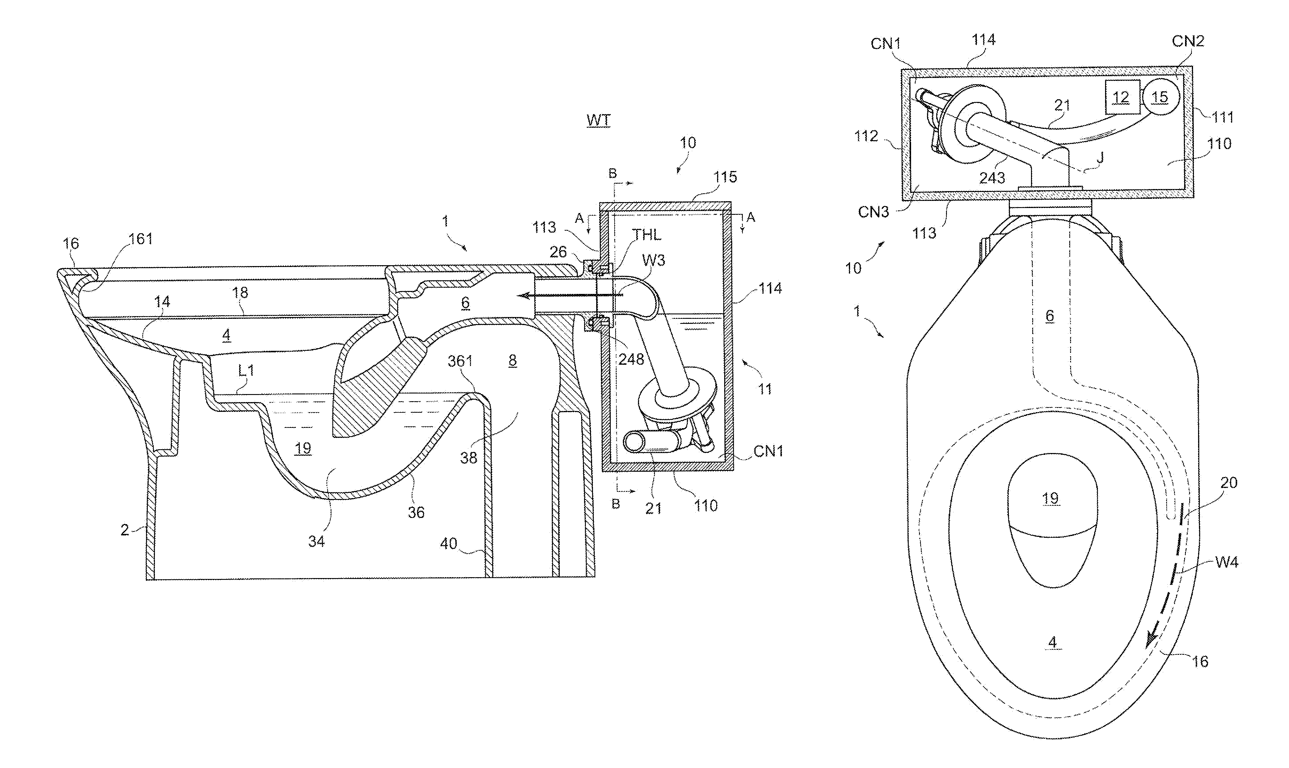
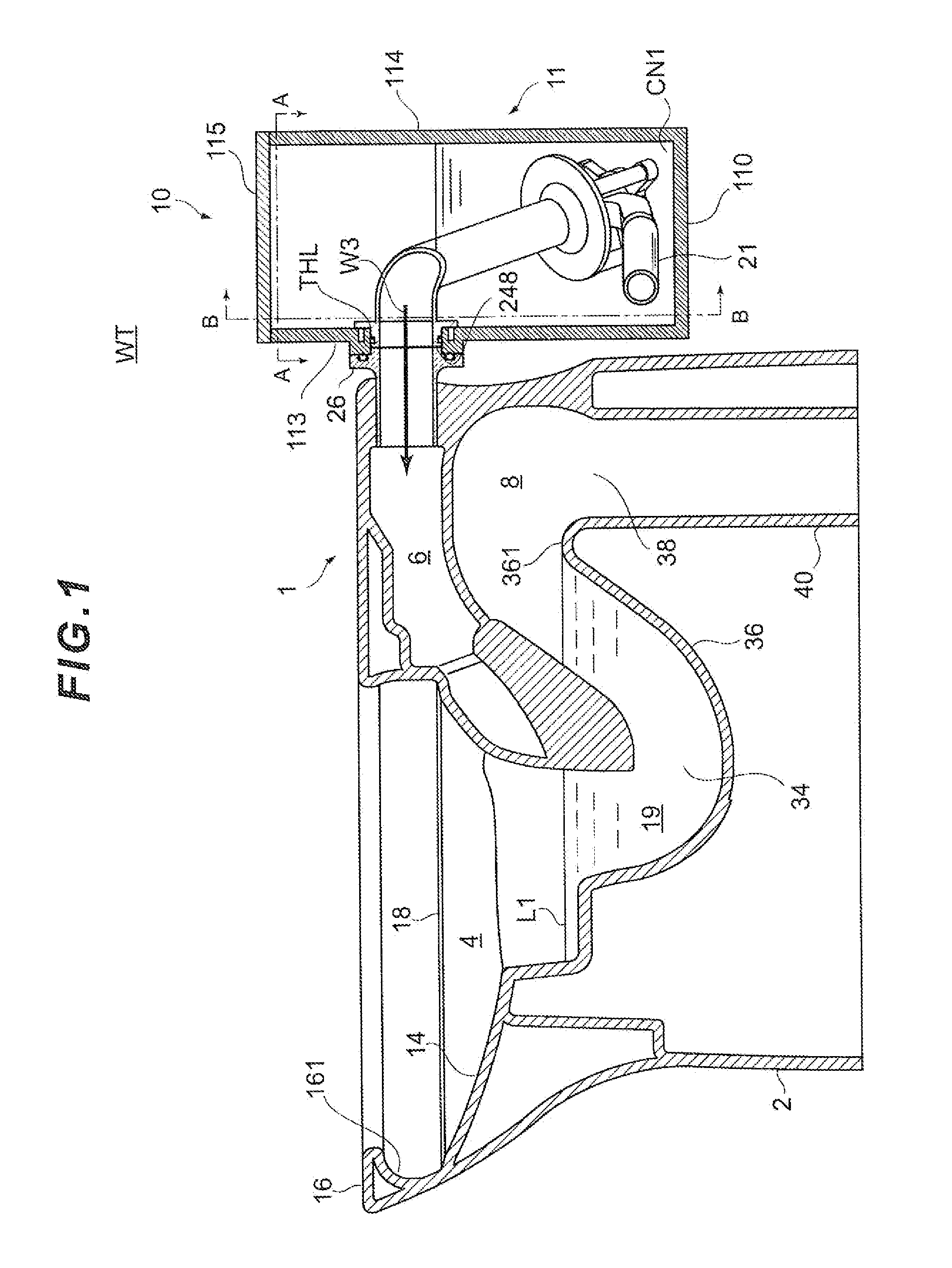
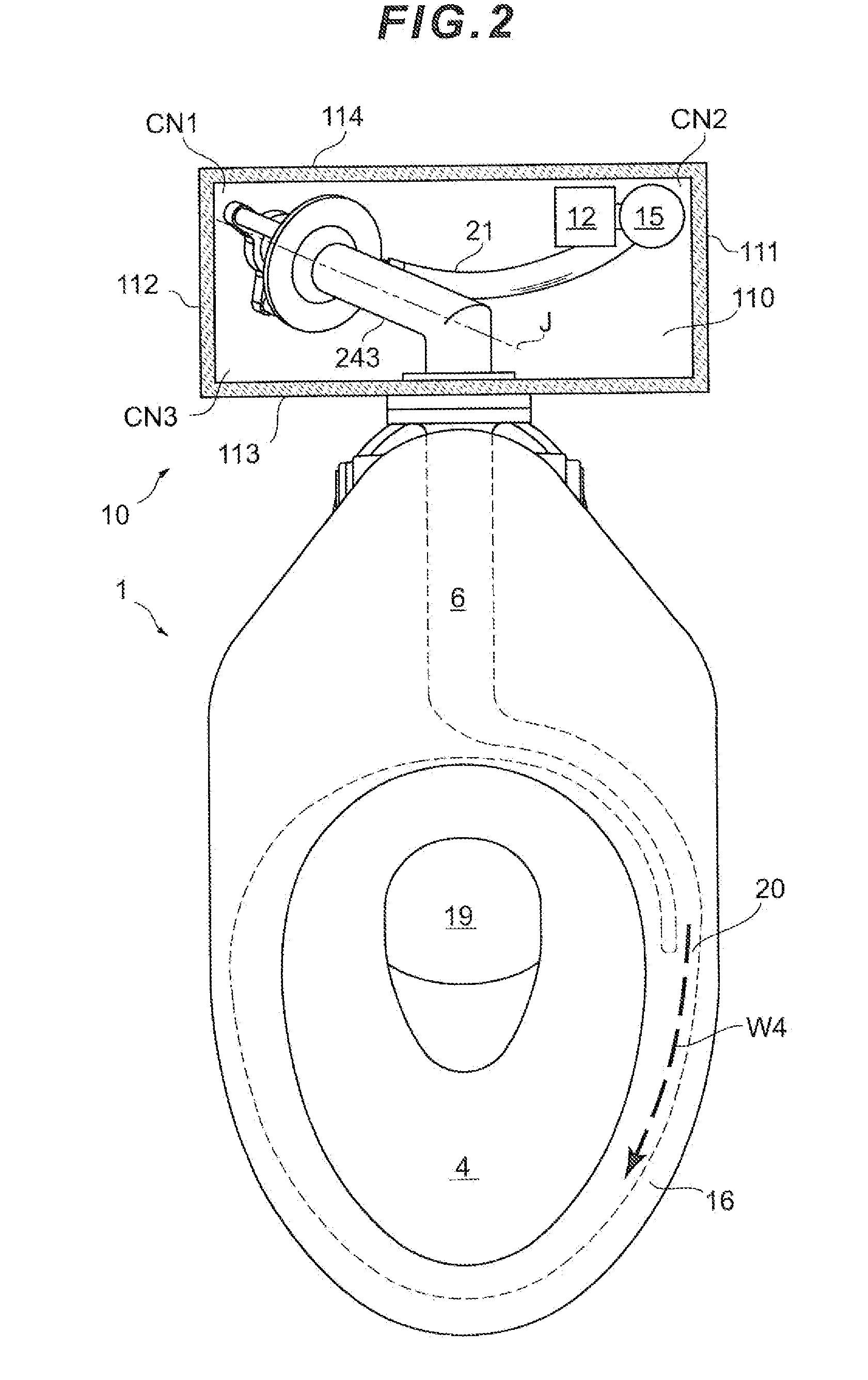
[0052]FIG. 1 is an outlined side cross-sectional view of a flush toilet device according to the present invention. FIG. 2 is an arrow view from an A-A direction in FIG. 1. FIG. 3 is an arrow view from a B-B direction in FIG. 1. FIG. 4 is a cross-sectional view illustrating inner shapes of a jet nozzle and a throat provided in the flush toilet device shown in FIG. 1.

[0053]As shown in FIGS. 1 and 2, a flush toilet device WT is provided with a flush toilet 1 and a flush water supply device 10. The flush toilet 1 is a ceramic with a glaze layer formed on the surface, a skirt portion 2 is formed at a lower part, and a bowl portion 4 is formed on a front side of an upper half. In addition, a water guide path 6 is formed at a back upper part (inside) of the flush toilet 1, and a discharge water trap portion 8 for discharging waste is formed at a back lower part. The flush water supply device 10 is a device for supplying flush water to the flush toilet 1 and is arranged behind the flush toi...

second embodiment

[0098]Next, a description will be given of a flush toilet device WTa according to the present invention with reference to FIGS. 6 and 7. FIG. 6 is an outlined side cross-sectional view of the flush toilet device WTa. FIG. 7 is an arrow view from a C-C direction in FIG. 6. Hereinafter, only different points of the flush toilet device WTa from the flush toilet device WT will be described, and descriptions of common points to those of the flush toilet device WTa which was described above will be appropriately omitted.

[0099]A flush toilet 1a of the flush toilet device WTa is different from the flush toilet 1 in a shape of a water guide path 6a formed therein. One end of the water guide path 6a opens at an upper surface 101a of the flush toilet 1a, and the opening functions as an inlet port 61a of water supplied from the tank 11a. A position, at which the inlet port 61a is formed, is a part of the upper surface 101a of the flush toilet 1a on the back side and at a center part in the righ...


PUM


Abstract

There is provided a flush toilet device capable of being configured in a compact size and supplying a sufficient flow amount of water to a toilet to reliably flush and discharge waste. According to the flush toilet device, a straight pipe portion of a throat which is arranged inside a tank is arranged in a state where a center axis thereof inclines with respect to a front-back direction of the tank when viewed from an upper side.

Description

BACKGROUND OF THE INVENTION[0001]1. Field of the Invention[0002]The present invention relates to a flush toilet device which receives waste egested by a user and discharges the waste with water.[0003]2. Background Art[0004]In the related art, a flush toilet device, in which a tank type or direct pressure type water supply mechanism is used as a mechanism for supplying flush water to the toilet which receives waste, has been widely distributed.[0005]The tank type water supply mechanism is designed such that water is reserved in advance in a tank and the water is supplied as flush water to the toilet. Such a tank type water supply mechanism has a problem that the size of the tank mounted on the flush toilet device increases since it is necessary to reserve all water, which is to be supplied as the flush water, in the tank.[0006]In addition, it is necessary to fill the tank with water up to a full water level after completion of the toilet flushing in order to prepare for next flushing...

Claims


Application Information

Patent Timeline
Patent Type & Authority Patents(United States)
IPC IPC(8): E03D1/00E03D1/08E03D11/08
CPCE03D11/08E03D1/085E03D2201/40
Inventor KITAURA, HIDEKAZUISHIMARU, RYOKOIWABATA, TOMOHIROOTA, YOSHIKIYOSHIOKA, TAKASHI
Owner TOTO LTD
Why Eureka
Try Eureka