Vehicle control system
- Summary
- Abstract
- Description
- Claims
- Application Information
AI Technical Summary
Benefits of technology
Problems solved by technology
Method used
Image
Examples
first embodiment
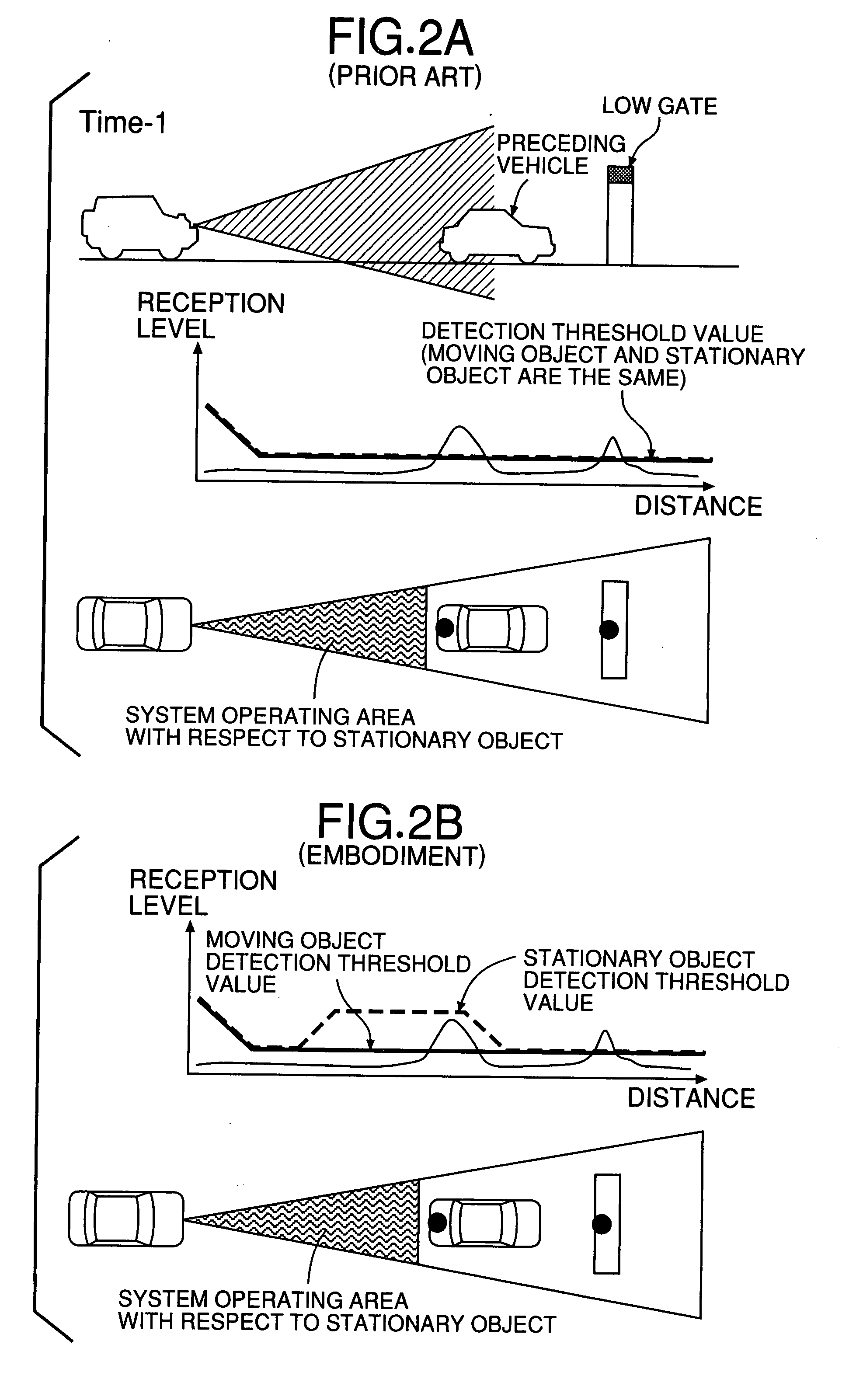
[0065] the present invention will now be described with reference to FIGS. 1 to 11.
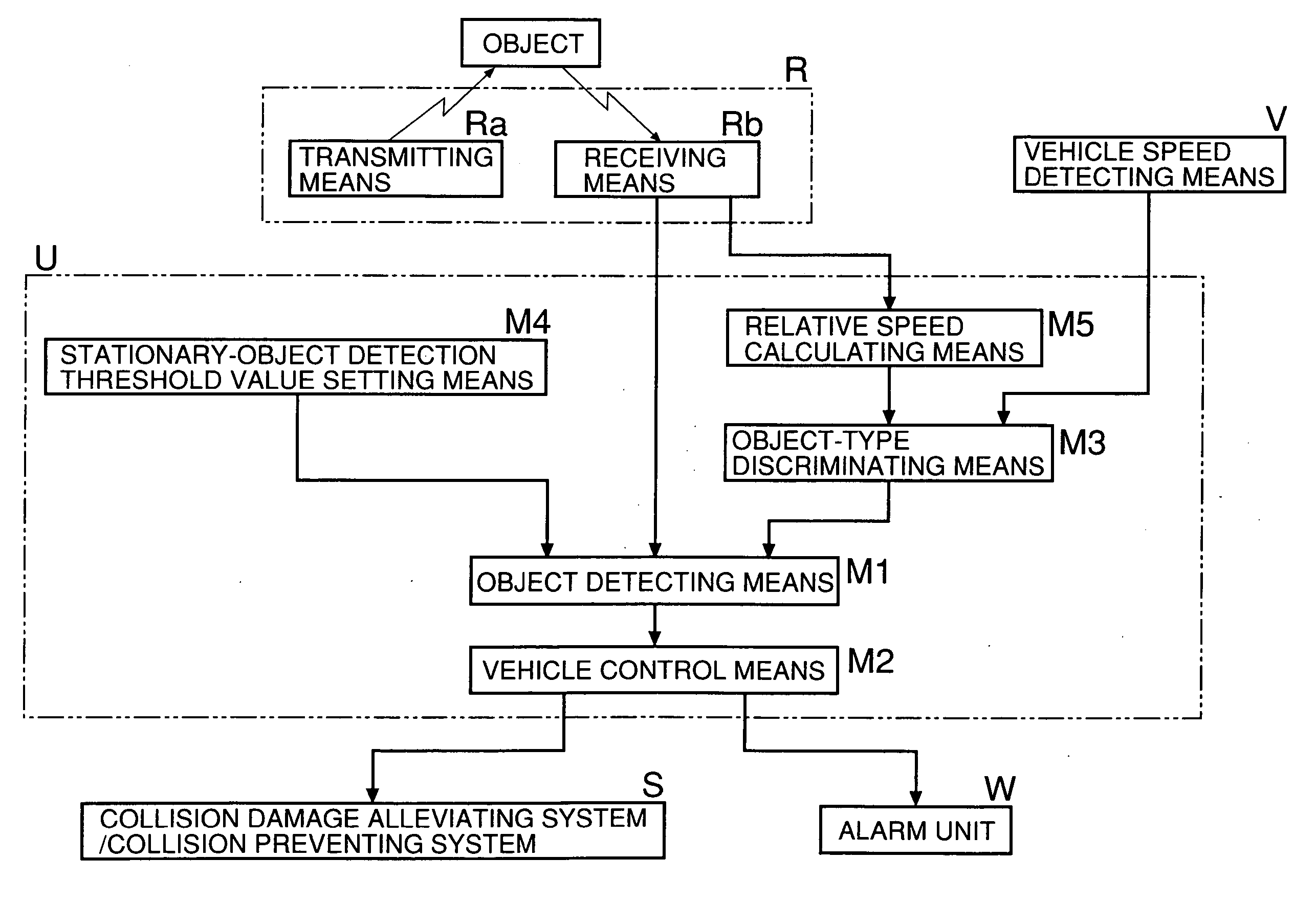
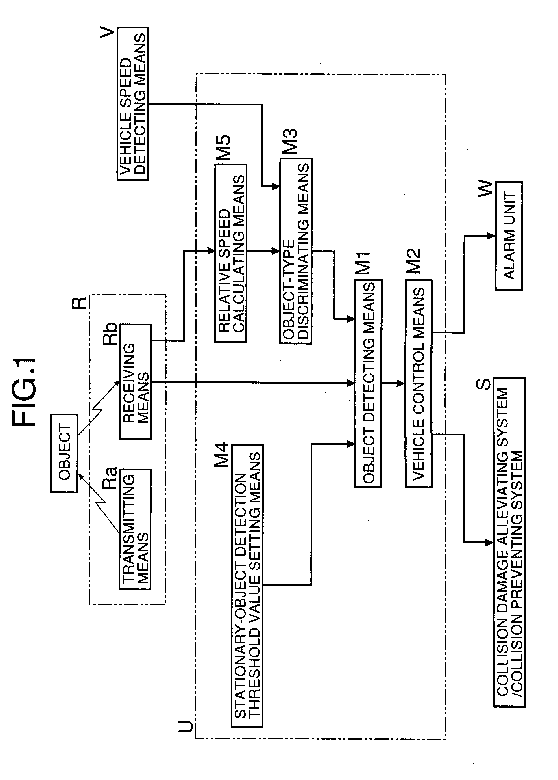
[0066] As shown in FIG. 1, a vehicle control system according to the first embodiment of the present invention comprises a radar device R which includes a transmitting means Ra for transmitting an electromagnetic wave and a receiving means Rb for receiving a reflected wave of the electromagnetic wave from an object. When a subject vehicle follows a preceding vehicle detected by the radar device R, if an inter-vehicular distance between the subject vehicle and the preceding vehicle decreases below a predetermined value resulting in an increased possibility of collision or an inevitable collision with a stationary object, the vehicle control system actuates a collision preventing system S and an alarm unit W. The collision preventing system S brakes the subject vehicle by automatic braking and the alarm unit W urges a driver to voluntarily brake. An electronic control unit U is connected to the radar de...
second embodiment
[0088] Next, the present invention will now be described with reference to FIGS. 12 to 14.
[0089] In the first embodiment of the present invention, if the reception level of the reflected wave from the stationary object is less than the stationary object detection threshold value at the stage of detecting the current target, such a target is deleted and regarded as having not been detected. In the second embodiment of the present invention, however, the extrapolated counter is set to “1” and the deletion of the target is not performed. Generally, the current data is predicted from the last data and used as extrapolated data. However, if the reception level of the reflected wave from the stationary object is less than the stationary object detection threshold value and the extrapolated counter is set to “1”, the prediction of the current data from the last data is not performed and the detected data is used as it is.
[0090] In the processing by the electronic control unit U, the extra...
third embodiment
[0094] the present invention will now be described with reference to FIGS. 15 to 21.
[0095] As shown in FIG. 15, a vehicle control system according to the third embodiment of the present invention comprises a radar device R which includes a transmitting means Ra for transmitting an electromagnetic wave, and a receiving means Rb for receiving a reflected wave of the electromagnetic wave from an object. When a subject vehicle follows a preceding vehicle detected by the radar device R, if an inter-vehicular distance between the subject vehicle and the preceding vehicle decreases below a predetermined value resulting in an increased possibility of collision or an inevitable collision with a stationary object, a collision preventing system S for braking the subject vehicle by automatic braking is operated, and an alarm unit W activates an alarm urging a driver to voluntarily brake. The radar device R of the third embodiment includes a laser radar device or a pulse radar device. An electro...
PUM
 Abstract
Description
Claims
Application Information
 - R&D
- Intellectual Property
- Life Sciences
- Materials
- Tech Scout
- Unparalleled Data Quality
- Higher Quality Content
- 60% Fewer Hallucinations
Browse by: Latest US Patents, China's latest patents, Technical Efficacy Thesaurus, Application Domain, Technology Topic, Popular Technical Reports.
© 2025 PatSnap. All rights reserved.Legal|Privacy policy|Modern Slavery Act Transparency Statement|Sitemap|About US| Contact US: help@patsnap.com


