Iliac extension with flared cuff

Active Publication Date: 2008-02-21
COOK MEDICAL TECH LLC
View PDF24 Cites 97 Cited by
  • Summary
  • Abstract
  • Description
  • Claims
  • Application Information

AI Technical Summary

Problems solved by technology

There remains, however, the problem of connecting this branched iliac stent graft with the bifurcated stent graft in the aortic region.
A particular problem with stent grafting in the common iliac region is that there is only a relatively short distance distally of the aortic bifurcation in which to make a connection and it is desirable that as secure as possible connection is provided.

Method used


Image

  • Iliac extension with flared cuff
  • Iliac extension with flared cuff
  • Iliac extension with flared cuff

Examples


Embodiment Construction

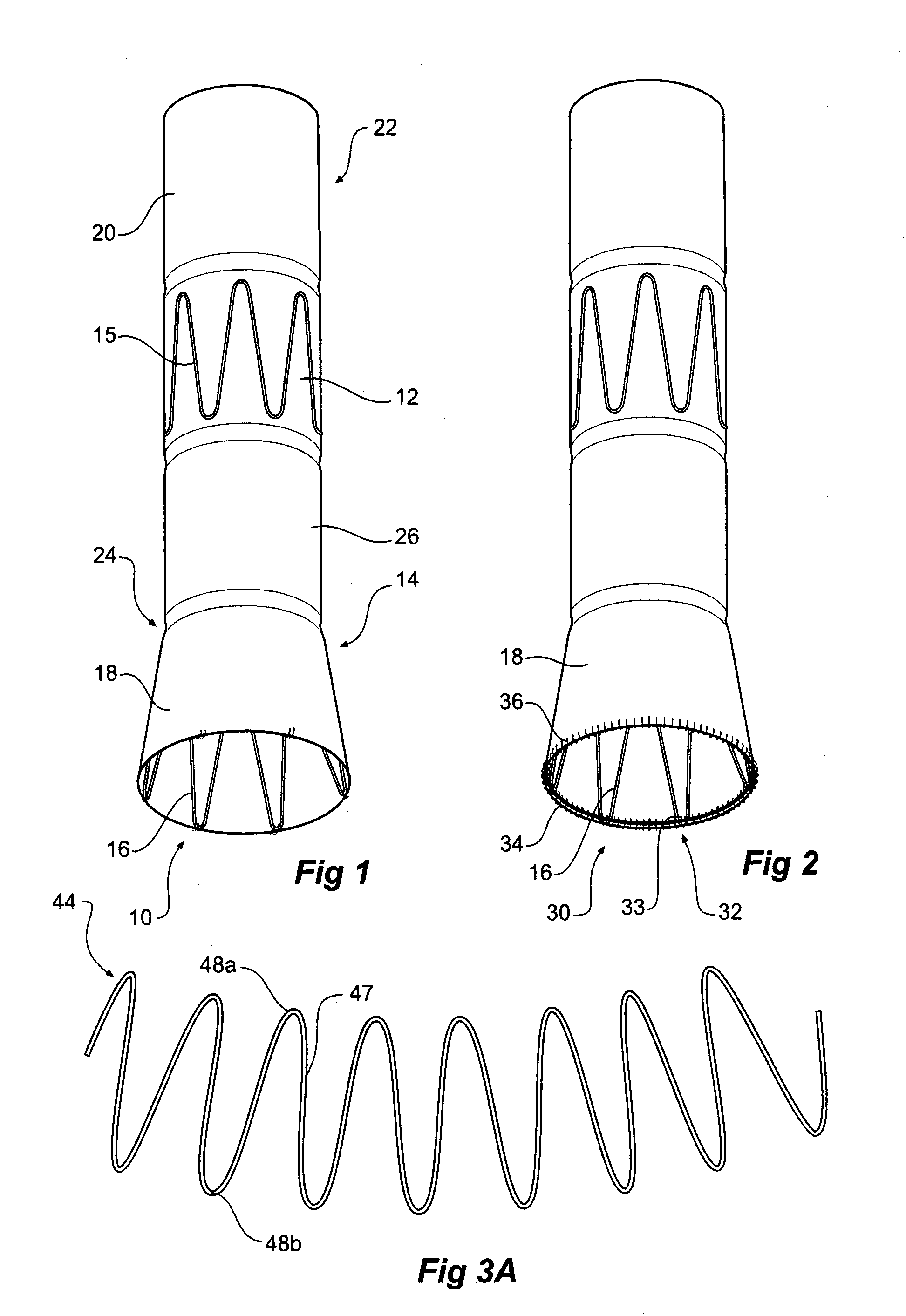
[0047] Now looking more closely at the drawings and more particularly FIG. 1 it will be seen that a first embodiment of leg extension 10 for a stent grafting system according to the present invention comprises a tubular body 12 of a biocompatible graft material with the tubular body supported by self expanding stents 15. A connection region 14 comprising a flared stent 16 in this embodiment covered by a graft material cover 18 is at the distal end 24 of the leg extension 10.

[0048] The tubular body has a external proximal sealing surface 20 at its proximal end 22. The external proximal sealing surface has self expanding stents within the tubular body. The distal end 24 also has a sealing surface 26. The distal sealing surface has self expanding stents within the tubular body. The external proximal sealing surface 20 is arranged to seal within the leg of a bifurcated stent graft and the distal sealing surface 26 is adapted to seal within the proximal end of a branched iliac stent gra...


PUM


Abstract

A leg extension ( 10 ) for a stent grafting system to connect between an aortic graft and an iliac graft. The leg extension is a tubular body ( 12 ) of a biocompatible graft material with self-expanding stents connected along the length of the tubular body and the tubular body having a distal end with a connection region. The connection region has a flared stent defining an external frusto-conical surface to provide a connection arrangement to engage within an internally flared portion of an iliac graft.

Description

CROSS-REFERENCE TO RELATED APPLICATIONS [0001] This application claims priority of provisional application Ser. No. 60 / 838,963, filed Aug. 18, 2006. INCORPORATION BY REFERENCE [0002] The following co-pending patent applications are referred to in the following description: [0003] PCT Patent Publication No. WO 98 / 53761 entitled “A Prosthesis and a Method Deploying a Prosthesis”[0004] U.S. Provisional Patent Application Ser. No. 60 / 686,252, entitled “Iliac Artery Stent Graft” and U.S. Non-Provisional patent application Ser. No. 11 / 444,688 and Publication No. US-2006-0287704-A1. [0005] U.S. Provisional Patent Application Ser. No. 60 / 838,776 filed on Aug. 18, 2006 herewith and entitled “Configuration of Branched Stent Grafts”[0006] U.S. Patent Application Publication No. US-2003-01 99967-A1, and PCT Patent Publication No. WO 2003-0821 53 entitled “Bifurcated Branch Vessel Prosthesis”[0007] U.S. Patent Application Publication No. US-2004-0082990-A1, and PCT Patent Publication No. WO 2004...

Claims


Application Information

Patent Timeline
Patent Type & Authority Applications(United States)
IPC IPC(8): A61F2/06
CPCA61F2/07A61F2002/067A61F2002/075A61F2250/0039A61F2230/0067A61F2220/0075A61F2230/005A61F2230/0054A61F2/89
Inventor HARTLEY, DAVID ERNESTDUCKE, WERNER DIETER
Owner COOK MEDICAL TECH LLC
Why Eureka
Try Eureka