Heat exchanger

Inactive Publication Date: 2008-02-28
DENSO CORP
View PDF8 Cites 12 Cited by
  • Summary
  • Abstract
  • Description
  • Claims
  • Application Information

AI Technical Summary

Benefits of technology

[0011] In view of this fact, the object of the present invention is to provide a heat exchanger in which the thermal distortion is reduced while, at the same time, the pressure resistance performance is secured.

Problems solved by technology

The difference in the amount of thermal expansion between the tubes and the insert is liable to generate thermal stress due to thermal distortion at the root (coupling) between the core plate and the tubes adjacent to the insert.
A repeated change in temperature and hence a repeated change in thermal stress poses the problem that the tubes in the neighborhood of the root may be broken.
In the anti-thermal distortion structure proposed in Japanese Unexamined Patent Publication No. 11-325783, however, the notch of the insert reduces the strength to hold the tubes.
As a result, the portion of the tube adjacent to the notch is deformed by expansion and may break.
The anti-thermal distortion structure proposed by Japanese Unexamined Patent Publication No. 11-237197 also poses a similar problem to Japanese Unexamined Patent Publication No. 11-325783 due to the fact that the tube holding strength of the expansion of the insert is reduced.

Method used


Image

  • Heat exchanger
  • Heat exchanger
  • Heat exchanger

Examples


first embodiment

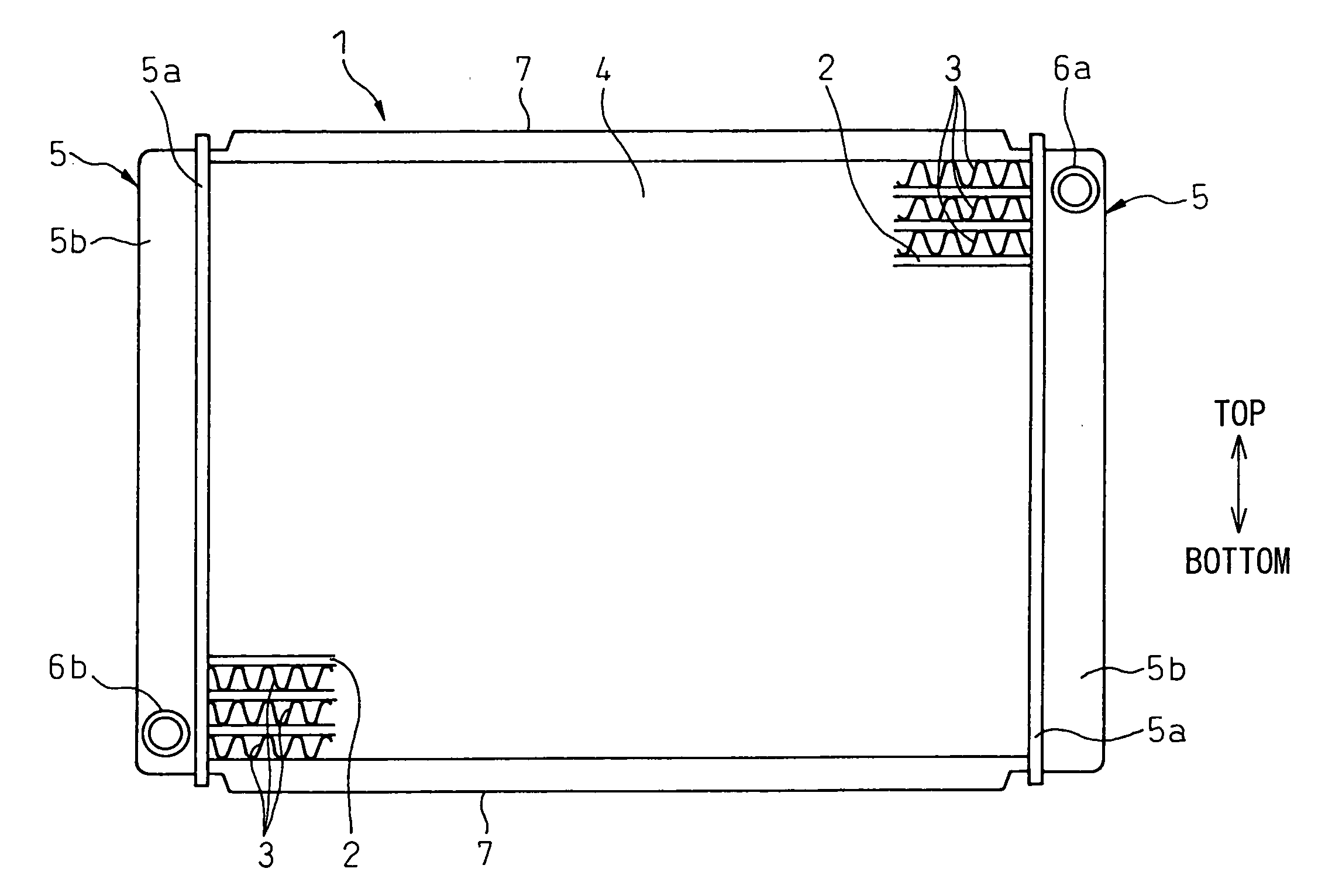
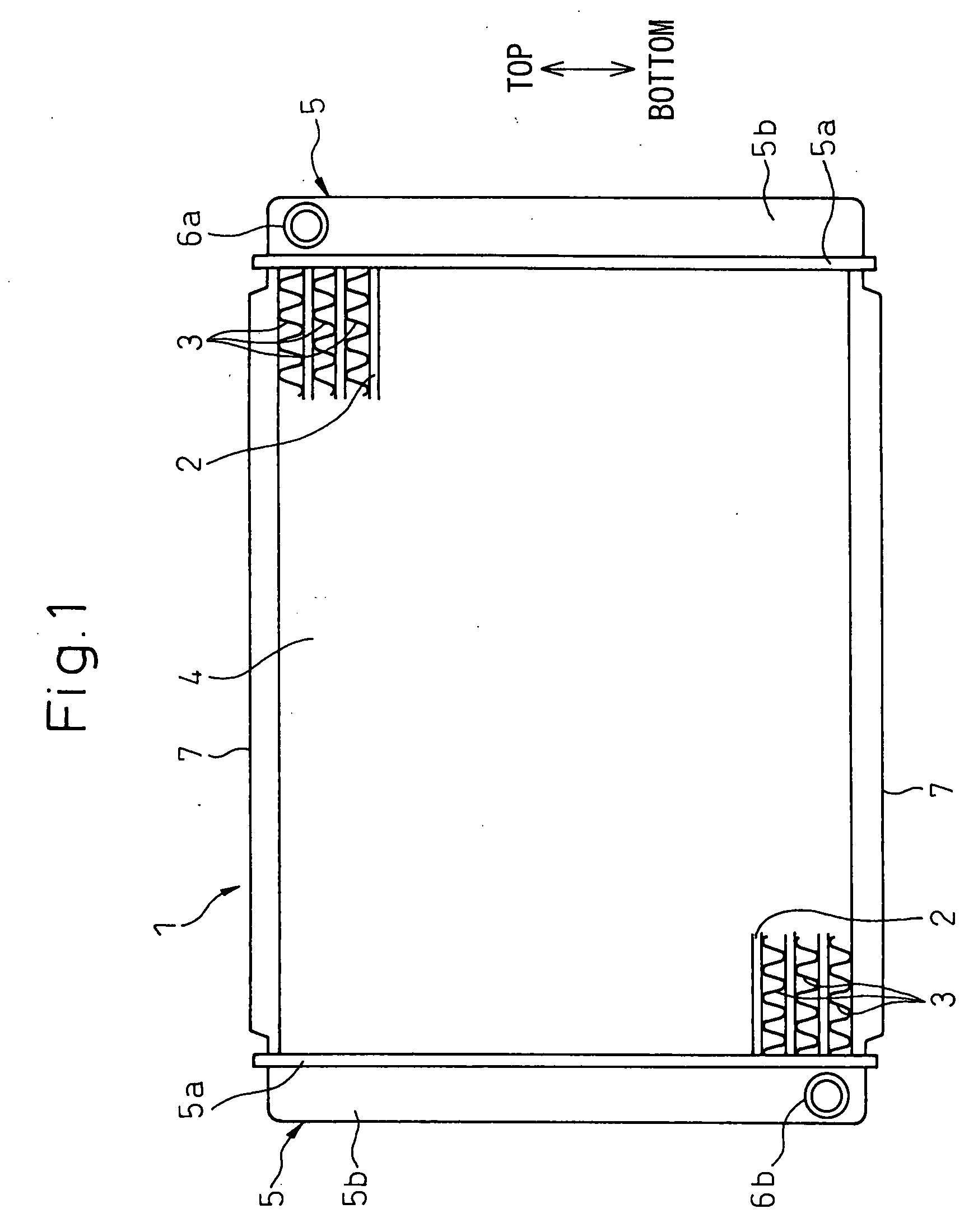
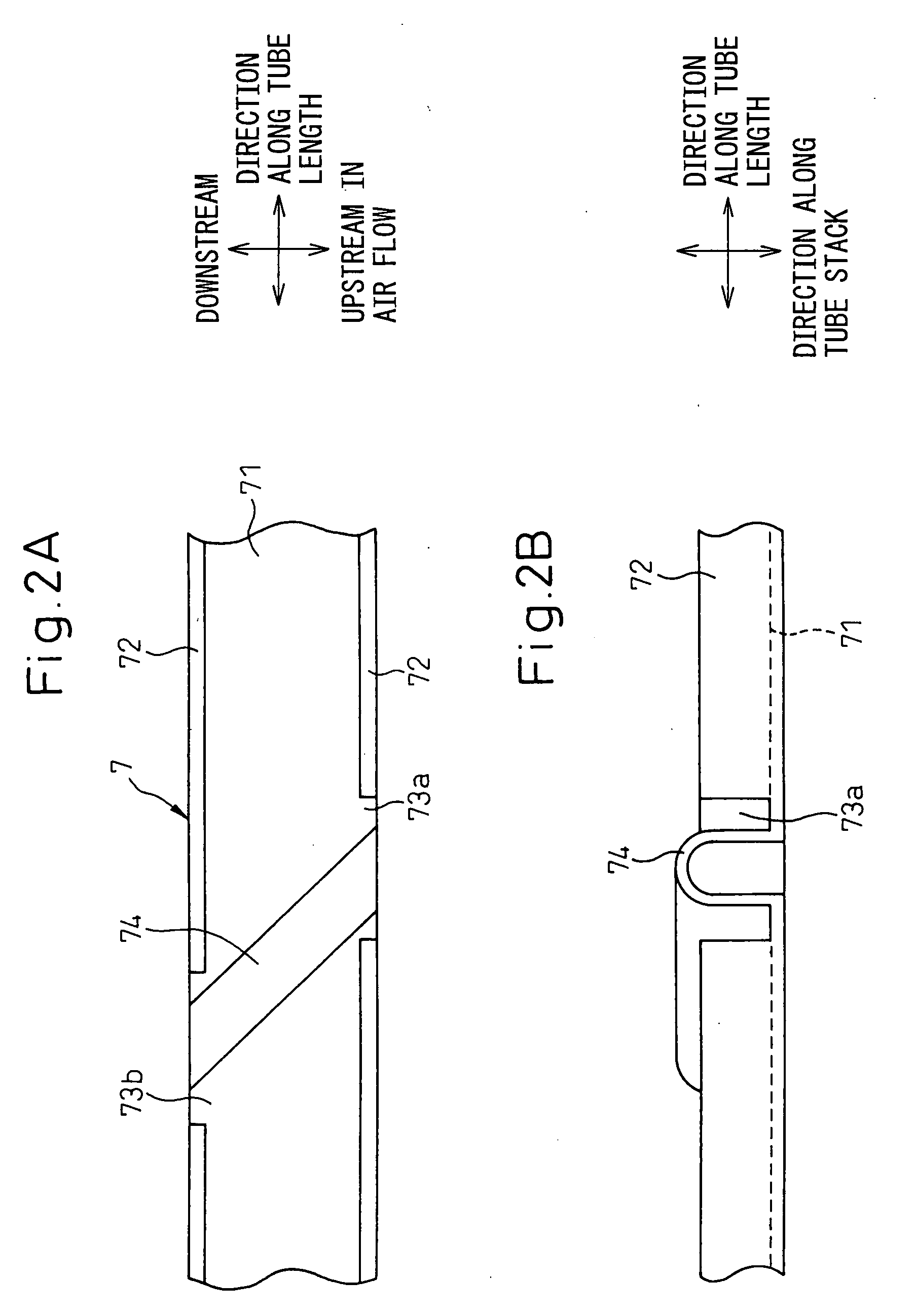
[0102]FIG. 2A is a plan view showing the insert 7 and FIG. 2B a front view of FIG. 2A. As shown in FIGS. 2A, 2B, the insert 7 includes a base portion 71 having a surface substantially parallel to the flat surface 2a of the tubes 2 and extending in the direction substantially in parallel to the length of the tubes 2 and a pair of ribs 72 projected from the ends of the base portion 71 along the air flow in the direction (direction of tube stack) substantially perpendicular to the base portion 71 and extending in a direction substantially parallel to the length of the tubes 2.

[0103] The pair of the ribs 72 of the insert 7 are formed with notches 73a, 73b, respectively, cut inward in the direction of the tube stack from the outer end of the ribs 72 in the direction of the tube stack. Also, the notch (hereinafter referred to the upstream side notch 73a) formed in the rib 72 on the upstream side in the air flow and the notch (hereinafter referred to as the downstream side notch 73b) form...

second embodiment

[0119] As a result, effects similar to those of the second embodiment are produced.

[0120] Further, in view of the fact that the two base portion-side expansions 74a, 74b are tilted in opposite directions in the direction of air flow, the spring back when molding the base portion-side expansions 74a, 74b can be reduced for an improved moldability.

[0121] Next, a fourth embodiment of the invention will be explained with reference to FIGS. 5A, 5B. In FIGS. 5A, 5B, component parts similar or identical to those of the second embodiment are designated by the same reference numerals, respectively, and are not described again. FIG. 5A is a plan view showing the insert 7 according to the fourth embodiment, and FIG. 5B is a front view of FIG. 5A.

[0122] As shown in FIGS. 5A, 5B, the base portion 71 of the insert 7 according to this embodiment is formed with two slits 75. According to this embodiment, the two slits 75 are arranged with the length thereof substantially parallel to the length of...

seventh embodiment

[0142] As a result, effects similar to those of the seventh embodiment described above are achieved.

[0143] Next, a ninth embodiment of the invention will be explained with reference to FIGS. 10A and 10B. In FIGS. 10A and 10B, component parts similar or identical to those of the seventh embodiment are designated by the same reference numerals, respectively, and are not described again. FIG. 10A is a plan view showing the insert 7 according to the ninth embodiment, and FIG. 10B a front view of FIG. 10A.

[0144] As shown in FIGS. 10A and 10B, the base portion 71 of the insert 7 according to this embodiment is formed with four notches 76. Of the four notches 76, two (hereinafter referred to as first notch portions 76c) are formed by cutting the base portion 71, from the upstream end toward the downstream end in the air flow. The two other notches (hereinafter referred to as a second notch portion 76d), other than the first notch portion 76c, on the other hand, are formed by cutting the b...


PUM


Abstract

A heat exchanger comprising: a core portion including a plurality of tubes; a pair of header tanks communicating with the tubes; and a pair of inserts arranged substantially parallel to the length of the tubes, and in such a manner as to contact the core portion at the ends of the core portion to transfer the heat from the core portion, and having the ends thereof supported on the header tanks; wherein a stress absorber to absorb the stress generated along the length of each insert is formed in the insert; wherein the stress absorber is formed over each insert from the upstream side to the downstream side in the air flow; and wherein the stress absorber is arranged in such a manner that the most upstream end and the most downstream end thereof in the air flow are not superposed, one on the other, along the direction of air flow.

Description

CROSS REFERENCE TO RELATED APPLICATION [0001] This application is a continuation-in-part application of Ser. No. 11 / 484,519 filed on Jul. 11, 2006, claiming priority of Japanese Patent Application Nos. 2006-281454 filed Oct. 16, 2006, 2006-157725 filed Jun. 6, 2006 and 2005-202807 filed Jul. 12, 2005.BACKGROUND OF THE INVENTION [0002] 1. Field of the Invention [0003] This invention relates to a heat exchanger or, in particular, to a heat exchanger effectively applicable to a multiflow radiator for cooling the cooling water of the internal combustion engine of an automotive vehicle. [0004] 2. Description of the Related Art [0005] The conventional multiflow radiator includes a core portion having a plurality of tubes,-a header tank communicating with the plurality of the tubes and an insert arranged at the end of the core portion for reinforcing the core portion. Also, the header tank is configured of a core plate coupled with the tubes and a tank body providing an internal space of t...

Claims


Application Information

Patent Timeline
IPC IPC(8): F28D1/00F28F7/00
CPCF28D1/05366F28D2021/0094F28F2265/26F28F9/0217F28F9/001
Inventor HIROSE, HIROKAZUKAMIYA, YOSHIHIKONINAGAWA, TOSHIHIDEOSAKABE, HIROYUKISUGITO, HAJIMEYAMAMOTO, MICHIYASUUNO, TAKAHIRO
Owner DENSO CORP
Why Eureka
Try Eureka