Welding slot sealing structure and welding method

Inactive Publication Date: 2008-10-02
HITACHI LTD
View PDF7 Cites 26 Cited by
  • Summary
  • Abstract
  • Description
  • Claims
  • Application Information

AI Technical Summary

Benefits of technology

[0018]According to the invention, there can be provided the welding slot sealing structure and the welding method fo

Problems solved by technology

This method, however, requires overlaying work such that the slot is filled with powder, which is melted by the laser beam applied while the powder is being charged, after the blade has been welded to the shroud or the disk.
This is because the fluid performance of impeller is degraded remarkably if the slot is left as it is.
According to the above-

Method used


Image

  • Welding slot sealing structure and welding method
  • Welding slot sealing structure and welding method
  • Welding slot sealing structure and welding method

Examples


Example

[0042]The laser welding of the blades and the shroud in accordance with the first embodiment will be described with reference to FIGS. 3 and 4.

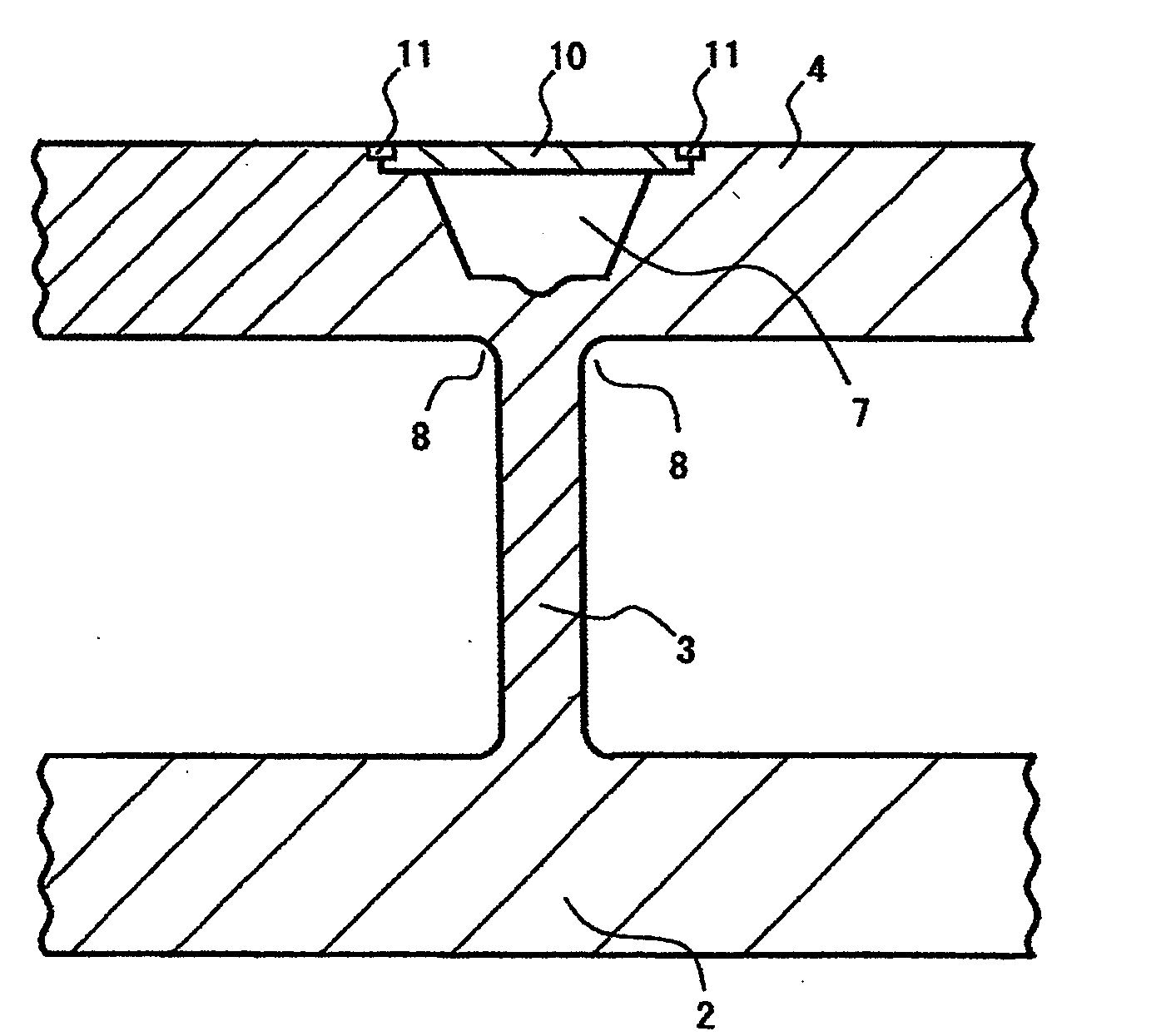
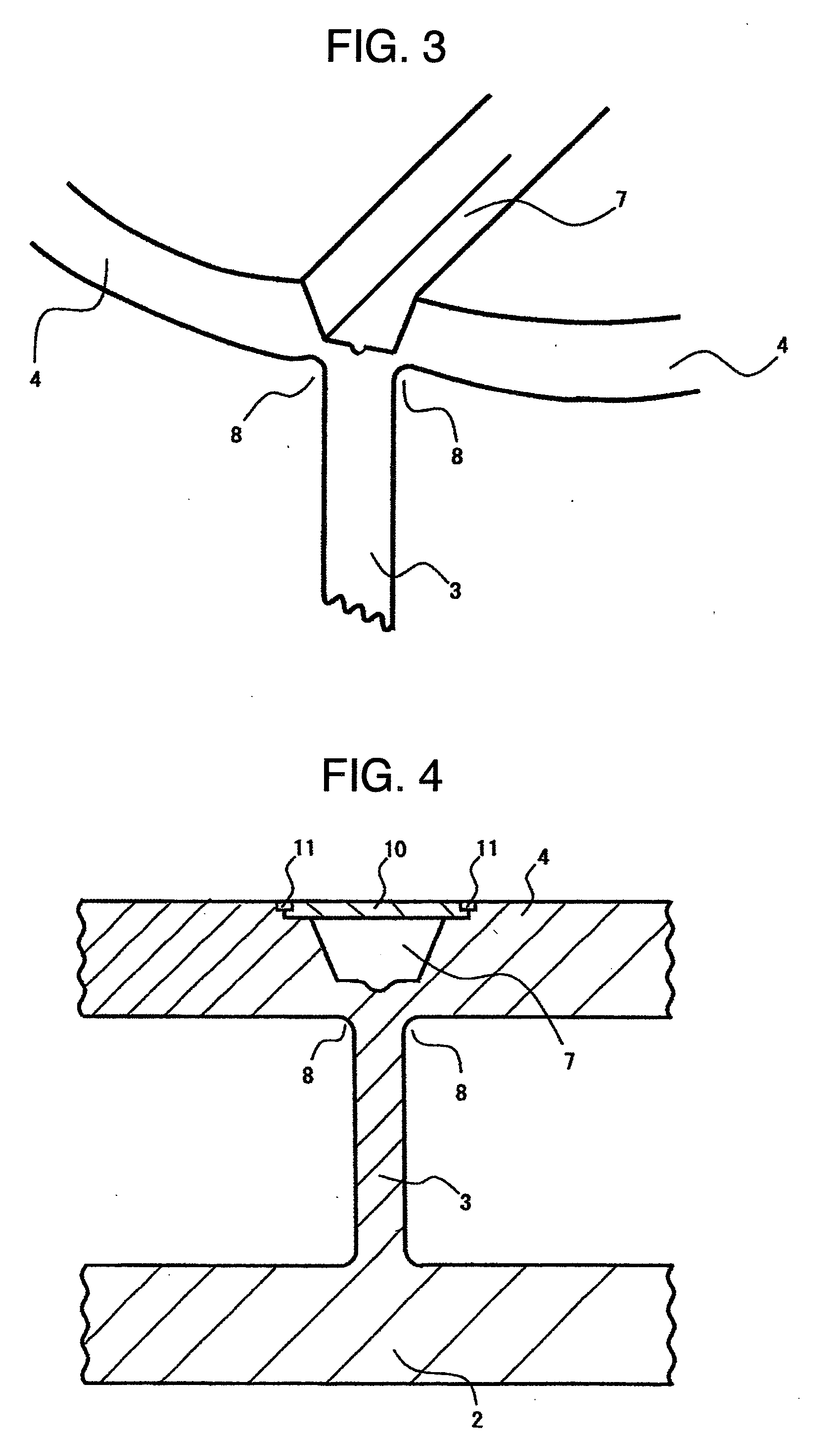
[0043]FIG. 3 is the perspective view of the blade and the shroud, which have been welded to each other. FIG. 4 is the partial sectional view of a welded part between the blade attached to the disk and the shroud.

[0044]In FIGS. 3 and 4, the slot 7 is provided in the shroud 4 on the opposite side from the blade 3 that is fixed to the disk 2 and brought into contact with the shroud 4. The blade 3 and the shroud 4 are welded to each other by applying a laser beam from the direction of the slot 7. The width of the slot 7 is preferably slightly larger than the thickness of the blade 3. By applying the laser beam from the surface of the shroud 4 in which the slot 7 is formed, the shroud 4 and the blade 3 are melted and integrated. Reference numeral 8 denotes a fillet formed by the welding of the blade 3 and the shroud, that is, a rounded part formed...

Example

[0047]The second embodiment of the invention is explained with reference to FIGS. 5 and 6.

[0048]FIG. 5 is the sectional view showing the state of the slot before the component is installed.

[0049]FIG. 6 is the sectional view showing the state of the slot after the component has been installed.

[0050]In FIGS. 5 and 6, the embodiment employs a method of fixing the component 10 for sealing the slot 7 by using bolts 12, not by welding. After the shroud 4 has been laser-welded to the blade 3, the component 10 is fitted in the grooves 9, which are located on the opposite side of the shroud from the blade 3 and formed on the opposite corners of the slot 7. In the lower surface of the groove 9, internal threads 13 are formed in advance. Also, in the component 10, holes 14 each having a diameter slightly larger than the bolt diameter are formed in advance.

[0051]The holes 14 are formed in the component 10 so that the bolts 12 are fitted at the internal thread positions in the groove 9 through t...

Example

Embodiment 3

[0052]The other embodiment of the invention will be described with reference to FIG. 7.

[0053]FIG. 7 is the sectional view showing the state of the slot after the component has been installed.

[0054]This embodiment employs a method of fixing the component 10 for sealing the slot 7 by brazing. A brazing filler is placed between the component 10 and the shroud 4. Then, the whole of the impeller 1 is heated to a predetermined temperature at which the brazing filler 15 melts. The melting of the brazing filler 15 makes the shroud 4 and the component 10 integral, by which the slot 7 formed in the shroud 4 can be sealed. As the brazing filler 15, a nickel-based or a gold-based metal is often used. Although the brazing filler is used in this embodiment, an adhesive can also be used. Brazing or bonding can reduce work man-hour as compared with the work of welding or fastening bolts.


PUM

PropertyMeasurementUnit
Thermal propertiesaaaaaaaaaa

Abstract

Blades are connected to the surface of a disk and slots are formed in the surface of a shroud, which is opposite from the other surface of the shroud where the blades are to be welded. The blades are arranged on the opposite surface from the slots and a laser beam is applied from the surface in which the slots are formed, to weld the shroud and the blades. If powder is melted and put in the slots formed for welding in the shroud to fill the slots, thermal distortion occurs. On the other hand, if the slots are left empty, a problem of degrading the fluid performance arises. To solve these problems, components are installed on the surfaces of the slots on the opposite side from the blades after the blades and the shroud in which the slots are formed are welded. Alternatively, the slots are filled with a material different from that of the shroud, such as a resin. With this configuration, distortion caused by welding heat can be reduced without degrading the fluid performance. This method can be applied to the case where the blades are formed on the surface of the shroud, not on the surface of the disk, and to the slots formed in the disk after the blades and the disk are laser-welded.

Description

BACKGROUND OF THE INVENTION[0001]The present invention relates to a welding slot sealing structure and its welding method.[0002]For an impeller attached to a centrifugal compressor or the like, welding is generally used when a blade is joined to a shroud. In manufacturing the impeller by welding, the height and shape of blade are restricted.[0003]For example, to manufacture an impeller that cannot be reached by hand and can not be welded, such liquid phase diffusion bonding as described in JP-A-5-202701 and JP-A-6-272696 may be used. Also, when an intricately-shaped impeller is manufactured, laser slot welding may be performed.[0004]In these welding processes, a shroud or a disk, to which the blade is welded, is formed with a slot in the surface on the opposite side from the blade, and a laser beam is applied from the slot side to melt and weld the shroud or disk and the blade. This method, however, requires overlaying work such that the slot is filled with powder, which is melted b...

Claims


Application Information

Patent Timeline
IPC IPC(8): F01D5/20B23K31/02B23K1/00B23K26/21B23K26/34F04D29/28F04D29/62
CPCB23K26/206B23K26/24B23K33/00B23K2201/001Y10T29/49968F04D29/026F04D29/2222Y10T29/49336F01D5/3061B23K2101/001F05D2230/234F05D2230/237F05D2230/64F05D2300/43F05D2300/603
Inventor IWASA, MASAAKITSUKAMOTO, TAKESHINOGIWA, HIDETOKUWANO, TETSUYAMAEDA, YOSHIHISAKOBAYASHI, HIROMIUDO, RYUJIRO
Owner HITACHI LTD
Why Eureka
Try Eureka