Switch points maneuvering device with manual control

a technology of manual control and maneuvering device, which is applied in the direction of railway signalling, transportation and packaging, roads, etc., can solve the problem of reducing the manual guiding force to be applied to the lever

Inactive Publication Date: 2008-02-28
ALSTOM TRANSPORT TECH SAS
View PDF6 Cites 3 Cited by
  • Summary
  • Abstract
  • Description
  • Claims
  • Application Information

AI Technical Summary

Benefits of technology

[0017] the input shaft is provided at one end with at least two longitudinal and circumferential apertures which are distributed angularly in a uniform manner, and the connection member includes a sliding bolt which is accommodated in the lever and a return spring which is capable of projecting a zone of the sliding bolt outside the lever towards the input shaft, which sliding bolt

Problems solved by technology

The technical problem is to reduce the manual guiding force to be applied to the lever during the operation f

Method used


Image

  • Switch points maneuvering device with manual control
  • Switch points maneuvering device with manual control
  • Switch points maneuvering device with manual control

Examples


Embodiment Construction

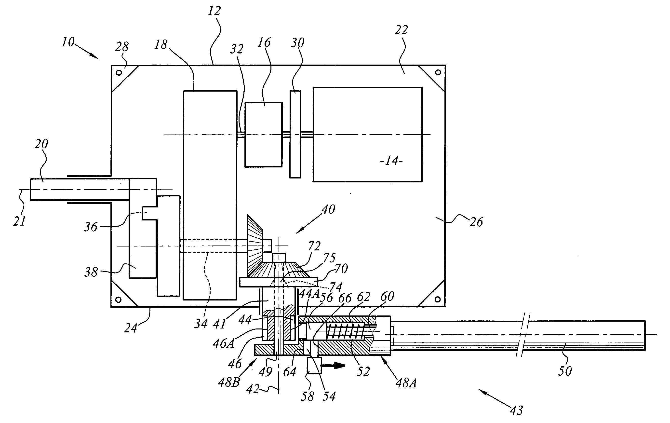
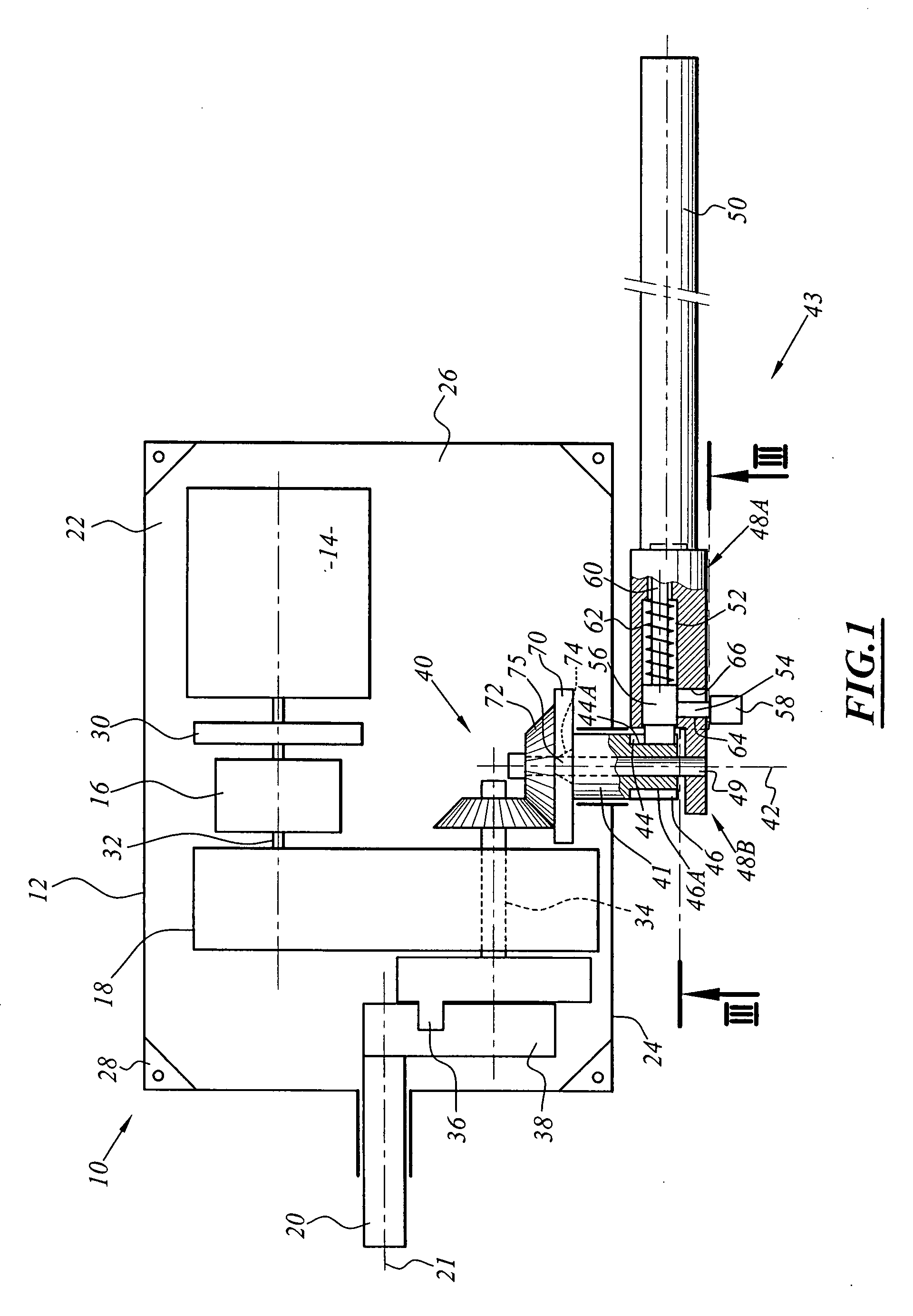
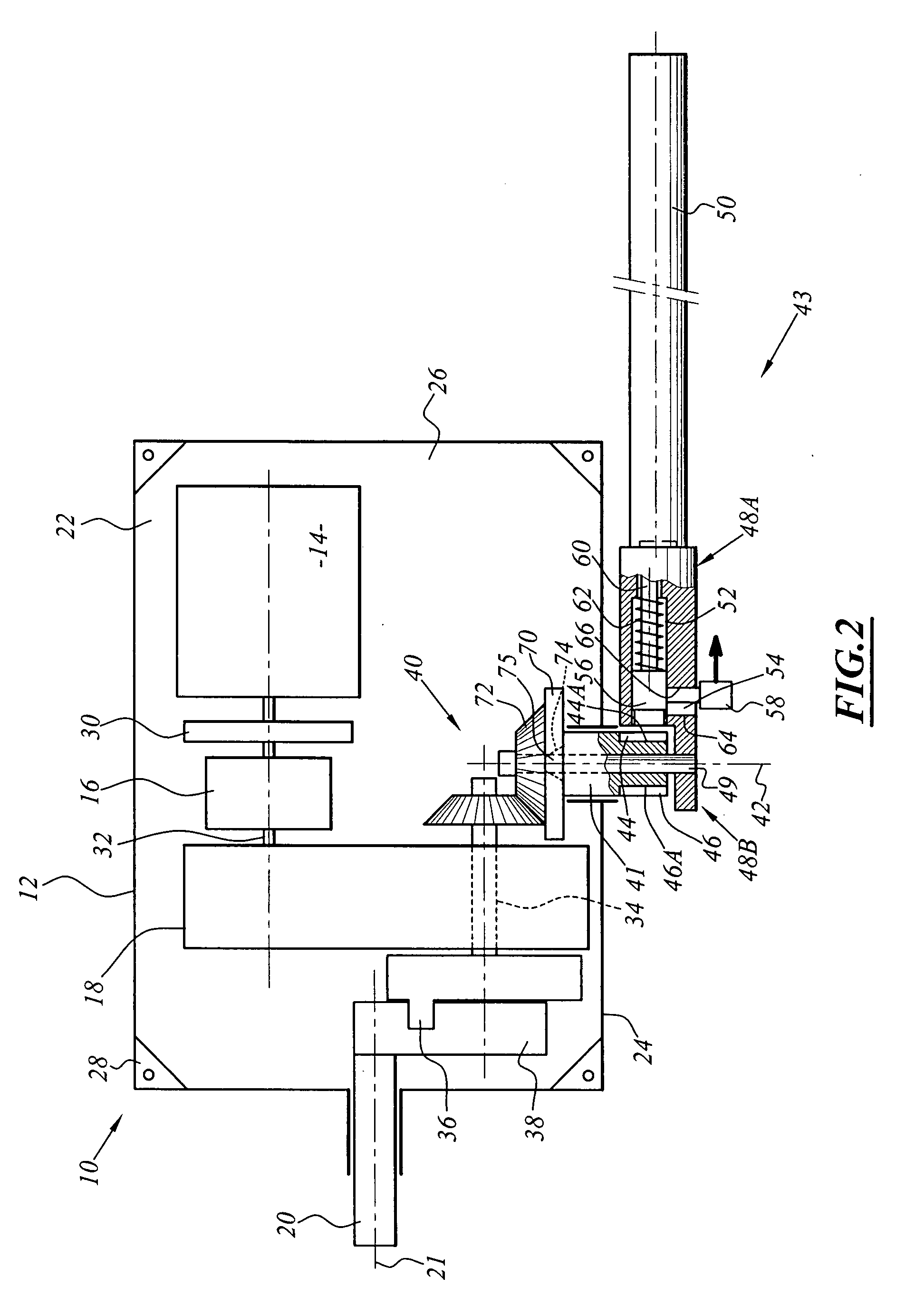
[0045] As illustrated in FIGS. 1 and 2, a device for activating a set of switch points 10 includes a housing 12 in which there are arranged a motor 14, a torque limiter 16 and a step-down gear 18 whose output is coupled to a guided member 20, in this case a rotating output shaft which is carried by the housing 12 and which extends therethrough.

[0046] The housing 12 may be produced, for example, from cast iron by means of casting. The housing 12 includes a base 22 which is bordered by a peripheral wall 24 which delimits, opposite the base, an opening 26 which is normally blocked by a removable cover. This cover extends substantially parallel with the base 22.

[0047] Fixing lugs 28 are provided at the periphery of the base 22 in order to fixedly join the activation device on the support thereof to the track.

[0048] The motor 14 is arranged in the housing at the side opposite that from which the output shaft 20 emerges. The output of the motor 14 is connected to the torque limiter 16 ...


PUM


Abstract

A device is provided for manually maneuvering a set of switch points, the device includes a housing which is intended to apply a force at a location of a set of rail switch points in order to move the set of switch points relative to the housing from a first switch points position to a second switch points position. The device also includes a guided member for controlling the set of switch points, which can be moved relative to the housing, a guiding member, which can also be moved relative to the housing, a transmission mechanism for driving the guided member in one direction when the guiding member moves in a first direction. The guiding member is capable of being moved in a second direction, opposed to the first direction, while the guided member remains fixed relative to the housing.

Description

[0001] This claims the benefit of French Patent Application No. 06 06587, filed on Jul. 19, 2006 and hereby incorporated by reference herein. TECHNICAL FIELD [0002] The present invention relates to a device for manually activating a set of switch points. BACKGROUND TO THE INVENTION [0003] A device of this type is used in particular to move the switch points rail of a set of switch points. To this end, a rod assembly which is formed by an assembly of sliding rods which are connected to each other is arranged along the set of switch points, and the switch points rail is connected to this rod assembly at several locations over the length thereof. At one end, the rod assembly is connected to an activation device which allows the movement of all the rods. [0004] An activation device of this type comprises, as known per se, a housing in which there is arranged an electric drive motor at the output of which a step-down gear is provided. The step-down gear is formed by a train of pinions wh...

Claims


Application Information

Patent Timeline
IPC IPC(8): E01B7/00
CPCB61L5/02B61L7/02
Inventor CARMES, FRANCIS
Owner ALSTOM TRANSPORT TECH SAS
Why Eureka
Try Eureka