
Dynamic electronic display system with brightness control

a technology of electronic display system and brightness control, which is applied in the direction of display means, signalling system, advertising, etc., can solve the problems of hazard for the person who steps, lack of additional cleaning properties, and the possibility of mat becoming wet and therefore ineffectiv

Inactive Publication Date: 2008-02-28
COLLIN PEEL
View PDF75 Cites 51 Cited by
  • Summary
  • Abstract
  • Description
  • Claims
  • Application Information

AI Technical Summary

Problems solved by technology

However, if a floor mat is utilized in an outdoor environment, such as an outdoor porch, or in an indoor environment that is adjacent to or near an outdoor entrance, such as an entry foyer of a home or business, the mat is likely to become wet and therefore not effective.
Additionally, if the mat surface becomes wet it may become slippery and thus cause a hazard for the person who steps on it.
Additional drawbacks with known floor mats exist that are directed to issues of customization for a particular purchaser and a lack of additional cleaning properties.
Whereas floor mats are known that may include a greeting on them, it is not currently known to allow for a particular purchaser to customize the displayed graphic so that the message is tailored to convey a particular message desired by the purchaser.
Currently, it is not known to provide a floor mat where an individual can customize the floor mat to display a particular message that they want to convey and in certain circumstances even change the floor mat's message they want to convey.
Such an advertising medium is limited, however, by the fact that the message is static and not easily changed.
However, there remain challenges to effectively and efficiently communicate to an audience by displaying visual advertising or messaging on the floor or ground.
Among these challenges is how to orient the content of a display for easy viewing and comprehension.
On the other hand, when an image is in horizontal space, problems relating to the orientation of the image may be presented.
This image will be upside down and therefore largely unintelligible to viewers walking south.
Such considerations may be further complicated by observing how differences in language affect image presentation.

Method used


Image

  • Dynamic electronic display system with brightness control
  • Dynamic electronic display system with brightness control
  • Dynamic electronic display system with brightness control

Examples


Embodiment Construction

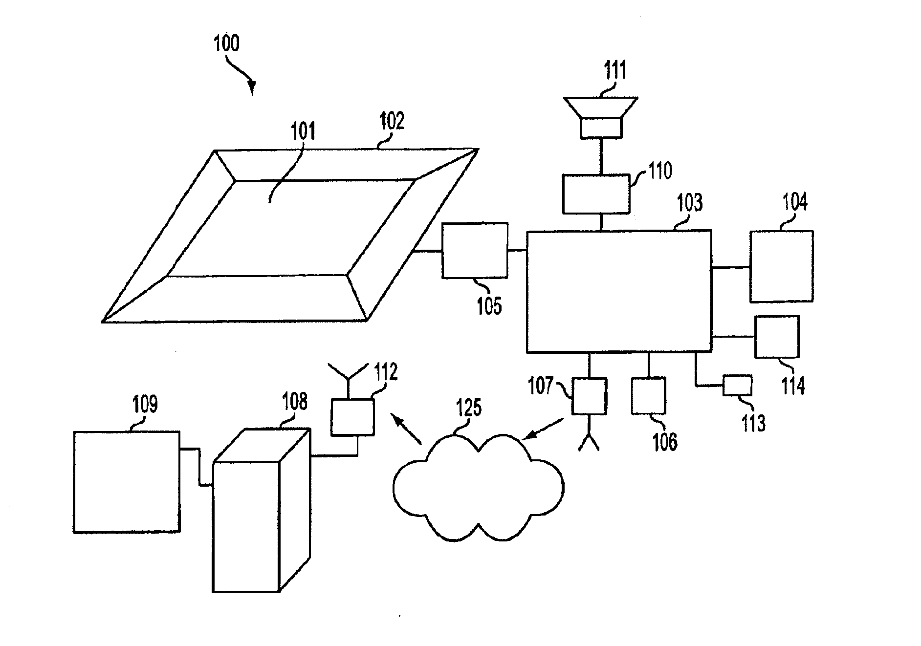
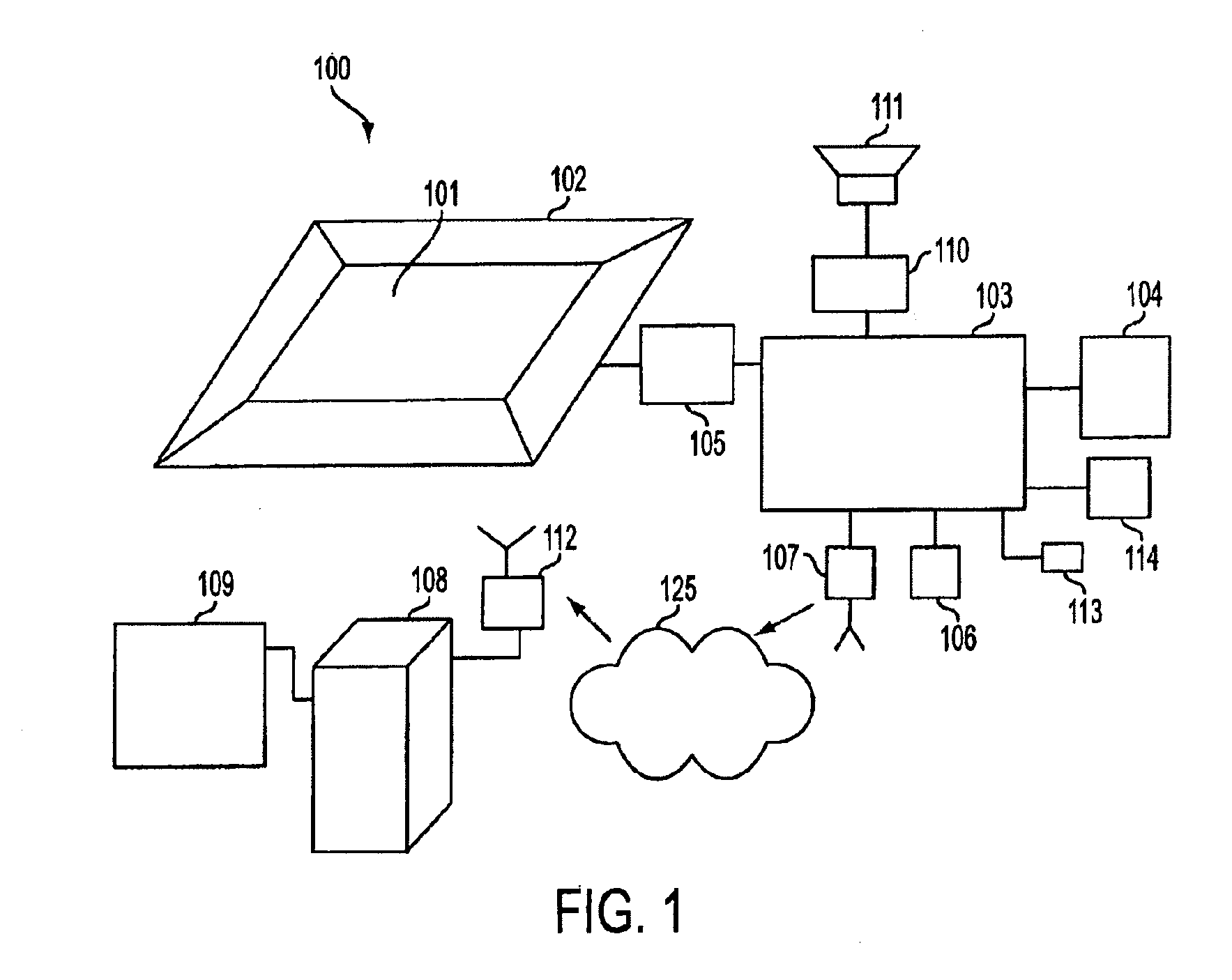
[0009] Embodiments of the present invention relate to a floor display system with among other features variable image orientation. More specifically, an image displayed by the floor display system may be oriented and / or reoriented depending on the perspective of viewers, in order to make the image more easily seen and understood. To orient and / or re-orient the image, the image may be rotated or otherwise moved or shifted.

[0010] The floor display system may be arranged in a public place, such as a commercial establishment or other public building, and be configured to display electronically modifiable arbitrary content, such as advertising or other informational content. In embodiments, the floor display system may be configured to detect an indication of the presence or activity of a person in the vicinity, and upon detecting the indication, perform a corresponding action in response. For example, upon detecting the indication of the presence of a person, the floor display system m...


PUM


Abstract

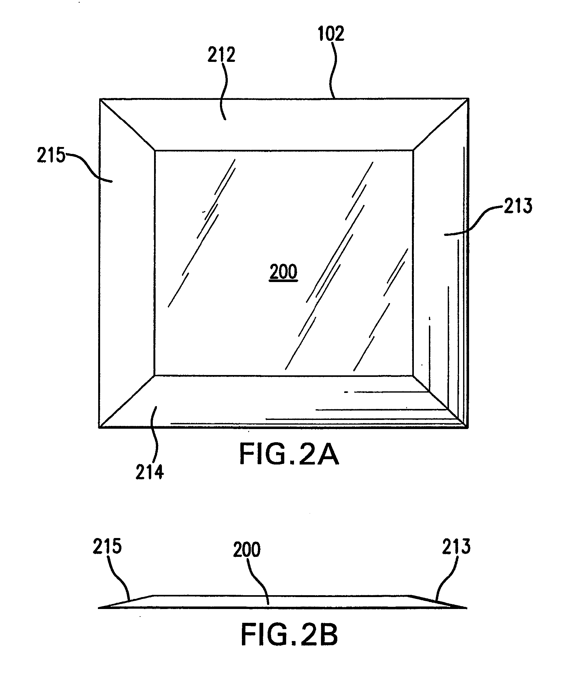
A floor display system, including a floor covering, an electronic display device associated with the floor covering, wherein the electronic display device is configurable to display electronically modifiable arbitrary content, a controller, and a sensing device coupled to the controller, wherein the brightness of an image displayed by the electronic display device is capable of being varied based on information received by the controller from the sensing device. The sensing device may include a proximity detector. The electronic display device may include a plurality of separate panels.

Description

CROSS-REFERENCE TO RELATED APPLICATIONS [0001] This application is a continuation-in-part of commonly owned copending application Ser. No. 11 / 316,928, filed Dec. 27, 2005, which is a continuation of U.S. application Ser. No. 10 / 454,631, filed Jun. 5, 2003, which claims the benefit under 35 U.S.C. 119(e) of U.S. provisional application 60 / 385,579 filed Jun. 5, 2002. Further, U.S. application Ser. No. 10 / 454,631 is a continuation-in-part of co-pending application Ser. No. 10 / 438,923, filed May 16, 2003, application, which is a continuation-in-part of co-pending application Ser. No. 10 / 285,639, filed Nov. 1, 2002, which is a continuation of application Ser. No. 10 / 137,357, filed May 3, 2002, and issued as U.S. Pat. No. 6,507,285 on Jan. 14, 2003, which is a continuation of application Ser. No. 09 / 767,846, filed Jan. 24, 2001, and issued as U.S. Pat. No. 6,417,778 on Jul. 9, 2002, which is a continuation of application Ser. No. 09 / 418,752, filed Oct. 15, 1999, and now abandoned, which i...

Claims


Application Information

Patent Timeline
IPC IPC(8): G08B5/00
CPCG06F3/041G06F3/1446G09F19/228G09G2380/06G09F19/22G06F3/011G06F3/0488
Inventor STRICKLAND, DAVECLELAND, SCOTT C.BLUM, RONALD D.
Owner COLLIN PEEL
Learn More