Pneumatic tire

a technology of pneumatic tires and cylinders, applied in the field of pneumatic tires, can solve the problems of easy occurrence of toe and heel wear, increased block deformation, etc., and achieves the effect of suppressing the deformation against action force upon evolution, sufficient edge effect, and easy maintenan

Inactive Publication Date: 2008-03-06
TOYO TIRE & RUBBER CO LTD
View PDF7 Cites 24 Cited by
  • Summary
  • Abstract
  • Description
  • Claims
  • Application Information

AI Technical Summary

Benefits of technology

[0012]According to the pneumatic tire of the present invention, the lateral groove disposed between the blocks on the endmost tread edge region is formed relatively shallowly, and both ends of the groove bottom concave portion are disposed inside the groove bottom, so that deformation against action force upon evolution is suppressed and evolution performance can be maintained. Also, since a width of the groove bottom concave portion is proper (wider than a common sipe), sufficient edge effect can be exhibited even when tire wear advances and, particularly, driving performance on a road covered with shallow snow is preferably maintained. In addition, since the width of the groove bottom concave portion is proper, when anteroposterior force is acted on the block, stress acting on an edge line of the block is alleviated, and thereby stepped wear is reduced. As a result, a pneumatic tire can be provided, which exhibits good driving performance particularly on a road covered with shallow snow while maintaining evolution performance, and also which is hard to produce irregular wear such as toe and heal wear.
[0013]In the pneumatic tire mentioned hereinbefore, it is preferable that a depth of the deepest part of the groove bottom concave portion is from 10 to 25% of the depth of the circumferential groove. By adjusting the deepest part of the groove bottom concave portion to such a depth, stress acting on the edge line of the block can be preferably alleviated when anteroposterior force is acted on the block, and also edge effect can be sure to be exhibited.
[0014]And also it is preferable that the block on the endmost tread edge region has a land portion sipe, which extends subparallel to the lateral groove disposed between the blocks and bends on the median side, and one end of the land portion sipe closes at a vicinity of the outer end of the block, while the other end thereof is open to the lateral groove. Since the other end of the land portion sipe is open to the lateral groove, the block edge is apt to move in a direction that cancels stepped wear, and therefore stepped wear in a longitudinal direction can be reduced. Also, since the land portion sipe extends subparallel to the lateral groove and bends on a median side, an edge component can be lengthened while maintaining a balance of block stiffness.
[0015]And also it is preferable that the grooves in the circumferential direction of the tire are composed of three circumferential grooves, the lateral groove disposed between these circumferential grooves has a depth from 40 to 70% of a depth of the circumferential groove and has a groove bottom sipe on the groove bottom of the lateral groove, and both ends of the groove bottom sipe are open. Herewith, the lateral groove disposed between the circumferential grooves has sufficient depth, and therefore the driving performance on a road covered with shallow snow becomes much better. In addition, since the lateral groove between the circumferential grooves is shallower than the circumferential groove, deformation by anteroposterior force of the block can be properly prevented, and also a sipe on the groove bottom of the lateral groove alleviates stress acting on an edge line of the block, when anteroposterior force is acted on the block. Therefore, stepped wear can be more decreased.

Problems solved by technology

However, such a pneumatic tire has relatively small blocks, and therefore the blocks are apt to be deformed.
This caused a problem of easy occurrence of toe and heel wear.
Also, there is a problem such that when relatively small blocks are formed on a tread edge region, deformation against action force upon evolution increases and evolution performance decreases.
However, in a tire described in Japanese Unexamined Patent Publication (Kokai) No. 10-86613, a groove width of the groove bottom sipe formed on the lateral thin groove was narrow, and therefore sufficient edge effect could not be exhibited when a tire wore out, and it was particularly hard to say that driving performance on a road covered with shallow snow was good enough.
Also, there was a problem such that when a groove bottom sipe with both closed ends was formed on the groove bottom of the lateral thin groove having a shallow bottom, suppression effect on irregular wear was little, since the width of the lateral groove was narrow, the depth was shallow and the groove width of the groove bottom sipe was narrow, so as to decrease effect by virtue of the groove bottom sipe.

Method used


Image

  • Pneumatic tire
  • Pneumatic tire
  • Pneumatic tire

Examples


example 1

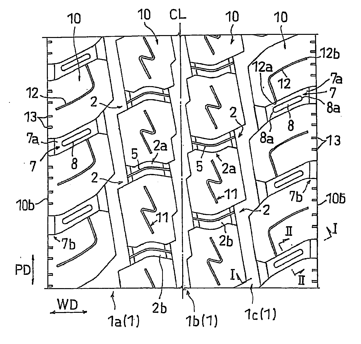
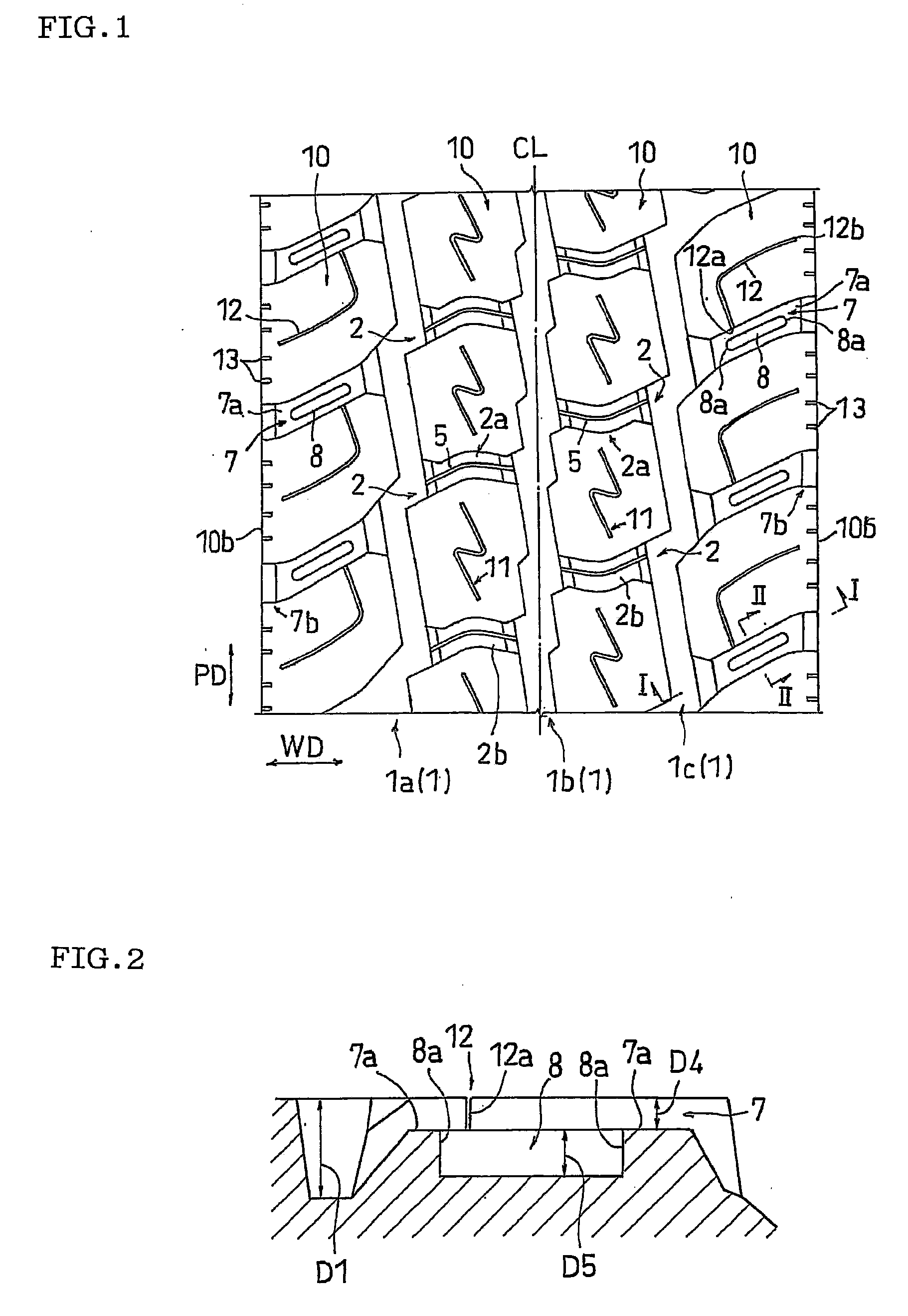
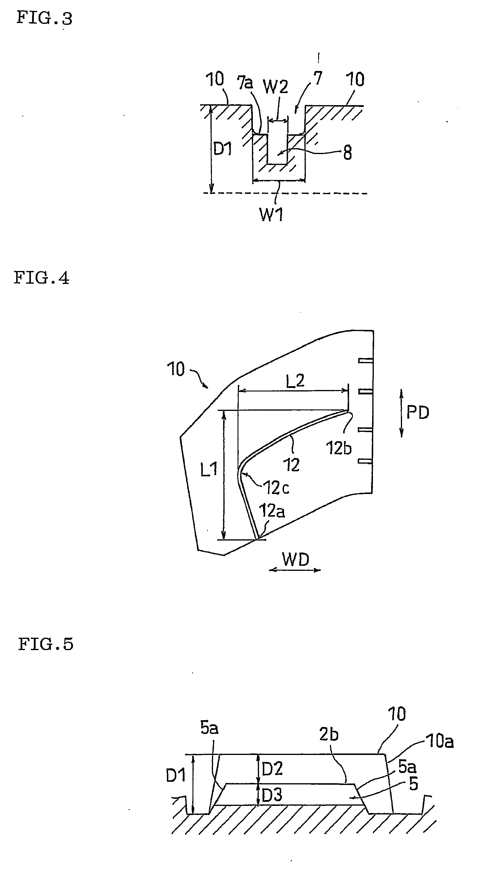
[0076]A radial tire having a size of 195 / 85R16 was produced by adjusting the depth of the circumferential groove 1 to 12 mm, and the groove width to 8.5 mm; the depth of the lateral groove 7 to 4.0 mm, the groove width to 6 mm and the length of the groove bottom to 5.8 mm; the depth of the groove bottom concave portion to 2.0 mm, the width to 2.0 mm and the length to 12 mm; the depth of the land portion sipe 12 to 6.5 mm, the groove width to 0.6 mm, L1=22 mm and L2=24 mm; the depth of the lateral groove 2 to 6 mm, the groove width to 6 mm and the curvature radius of the bend section to 10 mm; the size of the block on a median side to approximately 34 mm×34 mm; the depth of the groove bottom sipe 5 to 1.5 mm and the groove width to 0.6 mm; the depth of the land portion sipe 11 to 6.5 mm, the groove width to 0.6 mm, the circumferential length to 20 mm and the widthwise length to 7.5 mm in the tread pattern shown in FIG. 1. The evaluation results on respective performance of the tire w...

example 2

[0077]A radial tire was produced in the same manner as in Example 1 except for forming a groove bottom concave portion (rectangular shape) having a depth of 3 mm, width of 2.5 mm and length of 18 mm. The evaluation results on respective performance of the tire will be shown in Table 1.

example 3

[0078]A radial tire was produced in the same manner as in Example 1 except for forming a groove bottom concave portion (the shape is shown in FIG. 6(a)) having a depth of 1.5 mm, width of 1.5 mm and length of 5 mm. The evaluation results on respective performance of the tire will be shown in Table 1.


PUM


Abstract

A pneumatic tire provided with a tread pattern on which a plurality of blocks are formed with circumferential grooves which extend along a circumferential direction of the tire and lateral grooves which traverse the circumferential grooves, wherein the lateral groove disposed between the blocks on the endmost tread edge region has a depth from 10 to 50% of a depth of the circumferential groove to be traversed and has a groove bottom concave portion whose both ends in a longitudinal direction are disposed inside the groove bottom, and a width of the groove bottom concave portion, which is determined on the basis of the bottom plane of the groove bottom, is from 25 to 45% of a groove width of the lateral groove.

Description

BACKGROUND OF THE INVENTION[0001]1. Field of the Invention[0002]The present invention relates to a pneumatic tire provided with a tread pattern on which a plurality of blocks are formed with circumferential grooves, which extend in a circumferential direction of the tire, and lateral grooves.[0003]2. Description of the Related Art[0004]As a pneumatic tire which secures driving performance on a snowy road without forming a sipe in a block, a pneumatic tire provided with a tread pattern shown by FIG. 8 or FIG. 9 is known. Such a pneumatic tire commonly has 4 to 6 circumferential grooves 1 that extend along a circumferential direction of a tire, and has relatively small blocks 10 partitioned by the circumferential grooves 1 and lateral grooves 2.[0005]However, such a pneumatic tire has relatively small blocks, and therefore the blocks are apt to be deformed. This caused a problem of easy occurrence of toe and heel wear. Also, against a backdrop of the market, a demand on driving perfor...

Claims


Application Information

Patent Timeline
Patent Type & Authority Applications(United States)
IPC IPC(8): B60C11/03
CPCB60C11/0306B60C11/1369B60C11/125Y10S152/902B60C2011/1227B60C2011/1254Y10S152/03B60C2011/1213
Inventor OHARA, MASAAKI
Owner TOYO TIRE & RUBBER CO LTD
Why Eureka
Try Eureka