Pneumatic tire

a technology of pneumatic tires and tires, applied in the field of pneumatic tires, can solve the problems of pattern noise and deterioration of driving stability on dry road surfaces, and achieve the effects of improving snow performance, improving driving stability, and worsening the pattern nois

Inactive Publication Date: 2013-09-03
THE YOKOHAMA RUBBER CO LTD
View PDF9 Cites 6 Cited by
  • Summary
  • Abstract
  • Description
  • Claims
  • Application Information

AI Technical Summary

Benefits of technology

[0006]An object of the present invention is to provide a pneumatic tire which is capable of securing a driving stability on dry road surfaces and concurrently of improving snow performance without worsening its pattern noise.
[0008]The present invention ensures a sufficient drainage for the pneumatic tire, since each of the intermediate land parts and the shoulder land parts is provided with the multiple V-shaped grooves, and also because each thick groove part is extended in the tire width direction to communicate with any one of the main grooves and the outside of the ground contacting area depending on which land part the thick groove part belongs to. The present invention also ensures a sufficient edge effect for turning on the snow, since each thin groove part is extended in the tire circumferential direction. Such design improves snow performance of the pneumatic tire. In addition, the present invention causes the thin groove part of each V-shaped groove to terminate within a land part to which the V-shaped groove belongs. Such design prevents the reduction of the rigidity of each land part to a large extent, and consequently ensures the driving stability on dry road surfaces. Moreover, in the present invention, the V-shaped grooves are arranged in a way that each paired V-shaped grooves are opposed to each other in the tire circumferential direction with the connecting groove part being interposed between the vertices of the respective paired V-shaped grooves. This design avoids aligning the thick groove part of one of the paired V-shaped grooves with the thick groove part of the other of the paired V-shaped grooves in a straight line. Therefore, such design can avoid worsening the pattern noise of the tire.
[0009]In order to improve the driving stability on the dry road surfaces and the snow performance as well as to control the pattern noise, the following configurations should be preferably employed in the present invention. It is desirable that, in each V-shaped groove, an inclination angle θ1 of the thick groove part communicating with its corresponding main groove to the tire circumferential direction should be set at 40° to 70°. It is desirable that, in each V-shaped groove, an inclination angle θ2 of the thick groove part communicating with the outside of the ground contacting area to the tire circumferential direction should be set at 55° to 80°. It is desirable that, in each V-shaped groove, an inclination angle θ3 of the thin groove part to the tire circumferential direction should be set at 2° to 20°. Moreover, it is desirable that a distance L between the vertices of respective paired V-shaped grooves in the tire circumferential direction should be set at 1 mm to 6 mm.

Problems solved by technology

Increasing the number of groove in the tread part can possibly improve the snow performance of such pneumatic tire, yet, at the same time, its pattern noise as well as its driving stability on dry road surfaces tends to be deteriorated.

Method used


Image

  • Pneumatic tire
  • Pneumatic tire
  • Pneumatic tire

Examples


examples

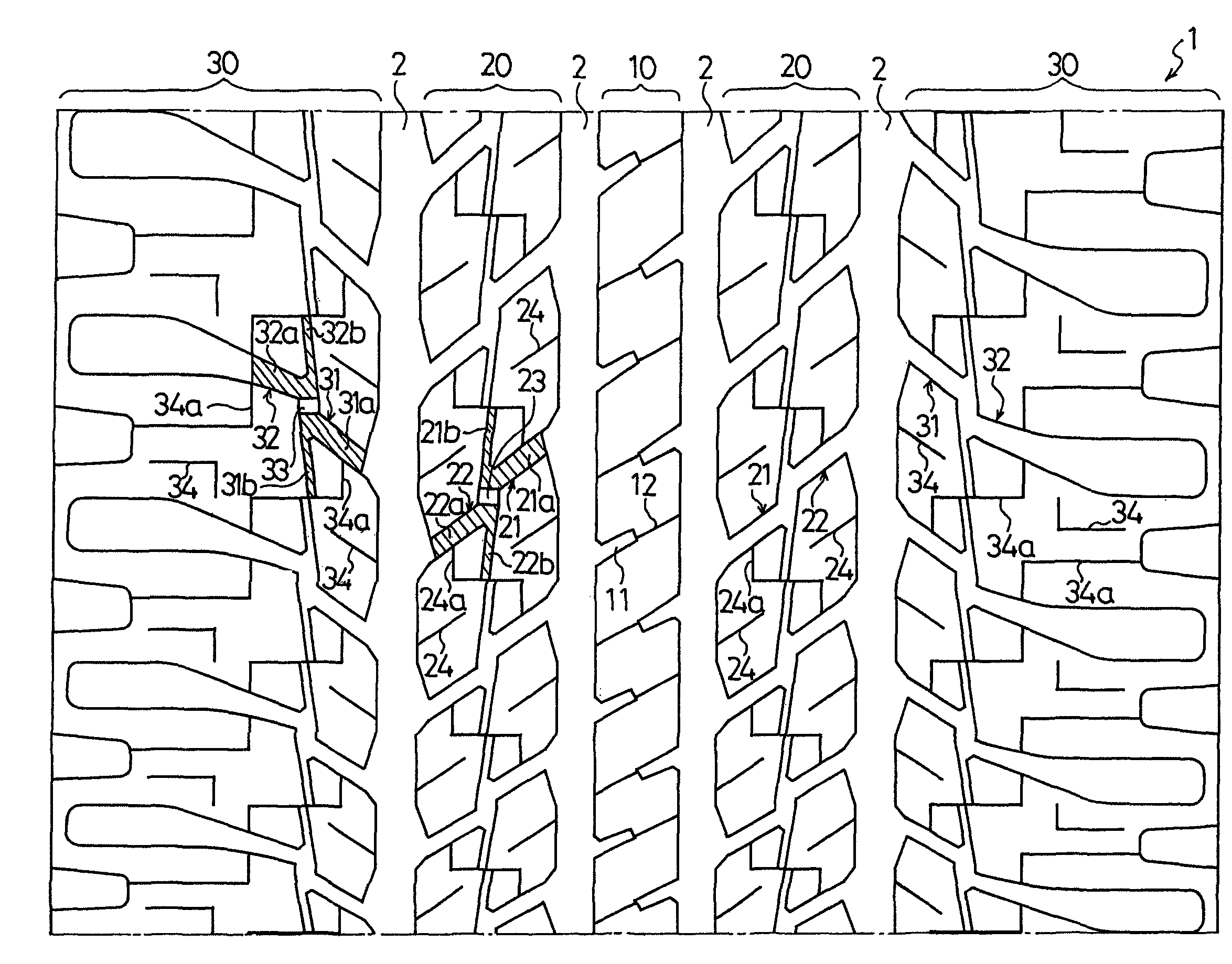
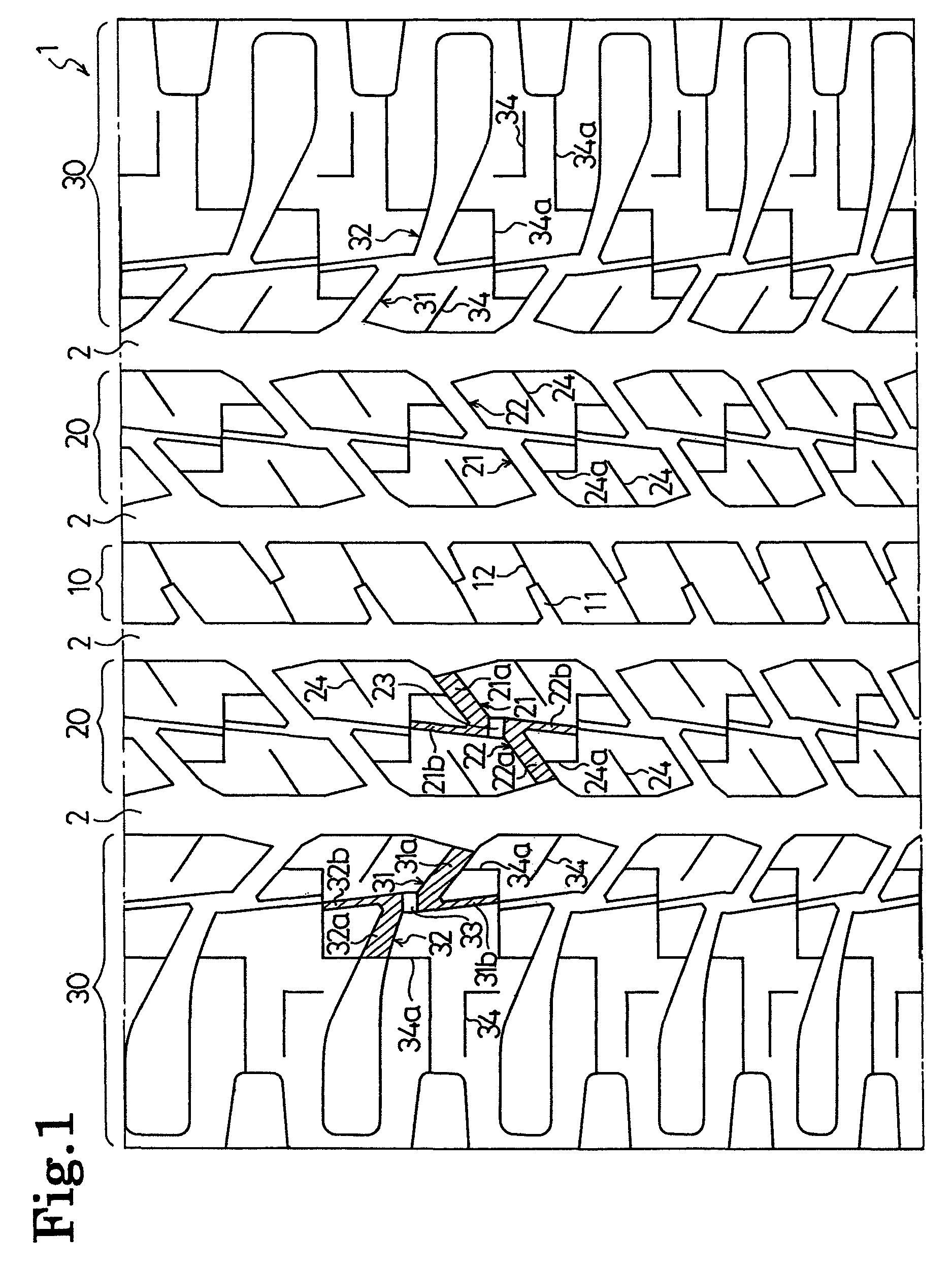
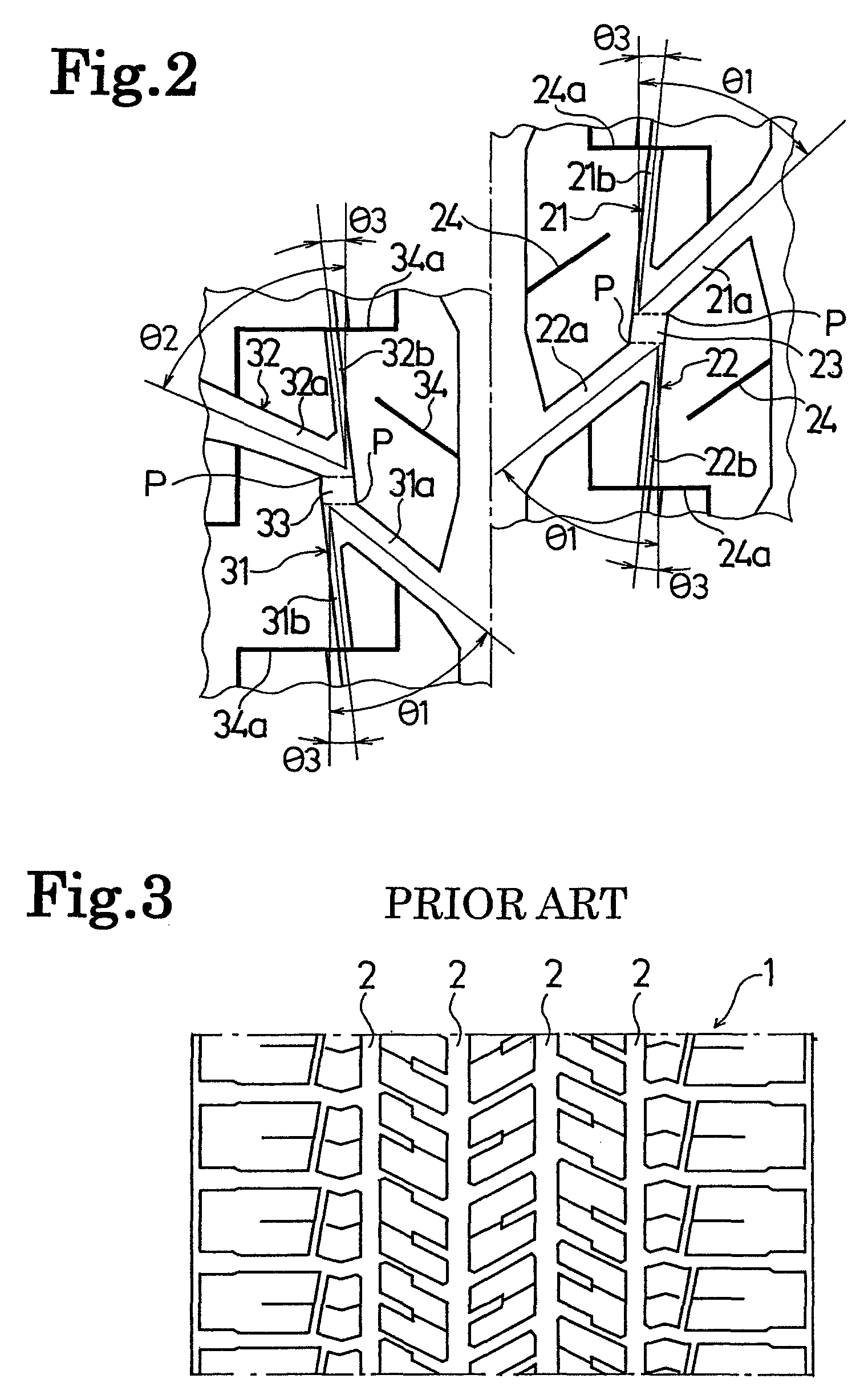
[0028]Pneumatic tires according to Examples 1 to 5 and Comparative Examples 1 to 2 (see Table 1) were produced with the following conditions. The tire size of the pneumatic tires was P245 / 60R20 (in TRA (Tire and Rim Association) Standards). Each pneumatic tire was provided with four main grooves each extending in its tread part in the tire circumferential direction so that the four main grooves partitioned the tread part into: a center land part; paired intermediate land parts located with the center land part being interposed in between; and paired shoulder land parts located with the center land part and the paired intermediate land parts being interposed in between. Each pneumatic tire had the following tread pattern. Each of the intermediate land parts and the shoulder land parts was provided with multiple V-shaped grooves each configured of a thick groove part extending in the tire width direction; and a thin groove part extending in the tire circumferential direction. These V-...


PUM


Abstract

Provided is a pneumatic tire which is capable of securing a driving stability on dry road surfaces and concurrently of improving snow performance without worsening its pattern noise. The pneumatic tire includes four main grooves each extending in its tread part in a tire circumferential direction, and the four main grooves partition the tread part into: a center land part; paired intermediate land parts located with the center land part being interposed in between; and paired shoulder land parts located with the center land part and the paired intermediate land parts being interposed in between. Each of the intermediate land parts and the shoulder land parts includes multiple V-shaped grooves each configured of: a thick groove part extending in a tire width direction; and a thin groove part extending in the tire circumferential direction. The V-shaped grooves are arranged in a way that each paired V-shaped grooves are opposed to each other in the tire circumferential direction with a connecting groove part being interposed between vertices of the respective paired V-shaped grooves. Each thick groove part communicates with the main grooves or the outside of a ground contacting area. Each thin groove part terminates within the land part.

Description

BACKGROUND OF THE INVENTION[0001]1. Field of the Invention[0002]The present invention relates to a pneumatic tire provided with four main grooves extending in the tire circumferential direction in its tread part. Specifically, the present invention relates to a pneumatic tire which has a secured driving stability on dry road surfaces and concurrently which has an improved snow performance without worsening its pattern noise.[0003]2. Description of the Related Art[0004]Various proposals have been so far made on a type of pneumatic tire which is provided with four main grooves each extending in the tire circumferential direction in its tread part, and the four main grooves partition the tread part into: a center land part; paired intermediate land parts located with the center land part being interposed in between; and paired shoulder land parts located with the center land part and the paired intermediate land parts being interposed in between (see Japanese patent application Kokai p...

Claims


Application Information

Patent Timeline
Patent Type & Authority Patents(United States)
IPC IPC(8): B60C11/13
CPCB60C11/0306B60C11/12B60C11/1369B60C2011/0388
Inventor IKEGAMI, TETSUO
Owner THE YOKOHAMA RUBBER CO LTD
Why Eureka
Try Eureka