
Reverse tricycle
A tricycle, reverse technology, applied in bicycles, motor vehicles, steering mechanisms, etc., can solve problems such as hidden safety hazards, insufficient strength, and inflexible driving, and achieve the effect of space guarantee for movement, increase in movement range, and stable vehicle driving.
- Summary
- Abstract
- Description
- Claims
- Application Information
AI Technical Summary
Problems solved by technology
Method used
Image

Examples
Embodiment 1
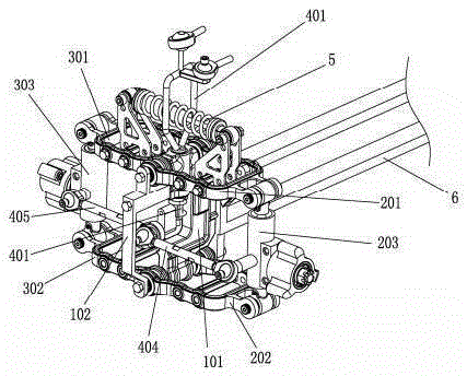
[0058] The universal steering mechanism of embodiment one such as Figure 8 As shown, it includes a left tie rod 404 and a right tie rod 405, and the two ends of the left tie rod 404 and the right tie rod 405 are respectively provided with rod end joint bearings;
[0059] The inner ring body 901 of the rod end joint bearing at the inner end of the left tie rod 404 is fixedly connected to the inner ring body 902 of the rod end joint bearing at the inner end of the right tie rod 405; the left tie rod 404 is connected through the inner ring body 903 of the rod end joint bearing at its outer end The left steering knuckle structure 203, the right tie rod 405 is connected to the right steering knuckle structure 303 through the inner ring body 904 of the rod end joint bearing at its outer end; The center hole of the inner ring body 901 of the rod end joint bearing at the inner end of the left tie rod 404 is also connected to the bottom end of the front steering column 401 . The inst...
Embodiment 2
[0061] The universal steering mechanism of embodiment two such as Figure 9 As shown, it includes a cross shaft 403, a left connecting rod 404, and a right connecting rod 405. The lower end of the front steering column 401 is hinged to the first shaft portion of the cross shaft 403, and the second shaft portion of the cross shaft 403 is connected to the The left connecting rod 404 and the right connecting rod 405 are hinged, the left connecting rod 404 connects the left steering knuckle structure 203 and the cross shaft 403, and the right connecting rod 405 connects the right steering knuckle structure 303 and the cross shaft 403. Describe the cross shaft 403. The left steering knuckle structure 203 and the left connecting rod 404 are also connected through a cross shaft, and the right steering knuckle structure 303 and the right connecting rod 405 are also connected through a cross shaft.
[0062] In the first embodiment, the main frame 1 includes a front bracket 102 and a m...
PUM
 Abstract
Description
Claims
Application Information