Twist-on wire wire connector with peelable covering

a twist-on wire and connector technology, applied in the direction of electrically conductive connections, coupling device connections, electrical apparatus, etc., can solve the problems of affecting the service life of the user, the twist-on wire connector is generally more time-consuming, and the sealant is sticky on the user but on other parts of the electrical system, so as to achieve the effect of quick form

Inactive Publication Date: 2008-03-06
THE PATENT STORE
View PDF1 Cites 6 Cited by
  • Summary
  • Abstract
  • Description
  • Claims
  • Application Information

AI Technical Summary

Problems solved by technology

On the other hand, the wires in the twist-on wire connector without a substance such as a protective sealant, if exposed to moisture, can result in a failed connection.
Some twist-on wire connectors carry a sticky sealant to overcome the moisture problem but these twist-on wire connectors are generally more time consuming to use when a wire connection needs to be rewired or reformed since to reconnect wires that have been encased in a sticky sealant care must be taken to first remove the sticky sealant from the wires before a reconnection is attempted.
Failure to do so can result not only in getting sticky sealant on the user but on other portions of the electrical system.
While these twist-on wire connectors provide for a solid encapsulation of the wire ends they do not allow for quick reforming or rewiring of a wire connection since the wires cannot generally be removed from the solidified epoxy in the twist-on wire connector.
Also, a time consuming process.
However, these type of twist-on wire connectors that use a sticky sealant require cleaning of the wires each time a wire connection needs to be reformed.
Although the art is replete with wire connectors that are covered with a waterproof sealant and the use of a gel that is squeezed or compressed about an electrical connection the art has not recognized the benefit of use of a free standing or unsqueezed mass of a cohering gel or a mass of a self adhereable gel in a gel state the internal spiral thread of a twist-on wire connector wherein the wires are quickly brought into low resistance electrical contact with each other in the presence of the gel and the gel is allowed to self heal to form a protective covering over the wire ends in the twist-on wire connector.

Method used


Image

  • Twist-on wire wire connector with peelable covering
  • Twist-on wire wire connector with peelable covering
  • Twist-on wire wire connector with peelable covering

Examples


Embodiment Construction

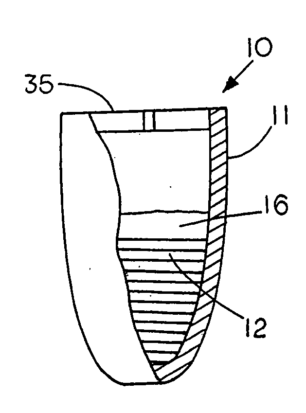
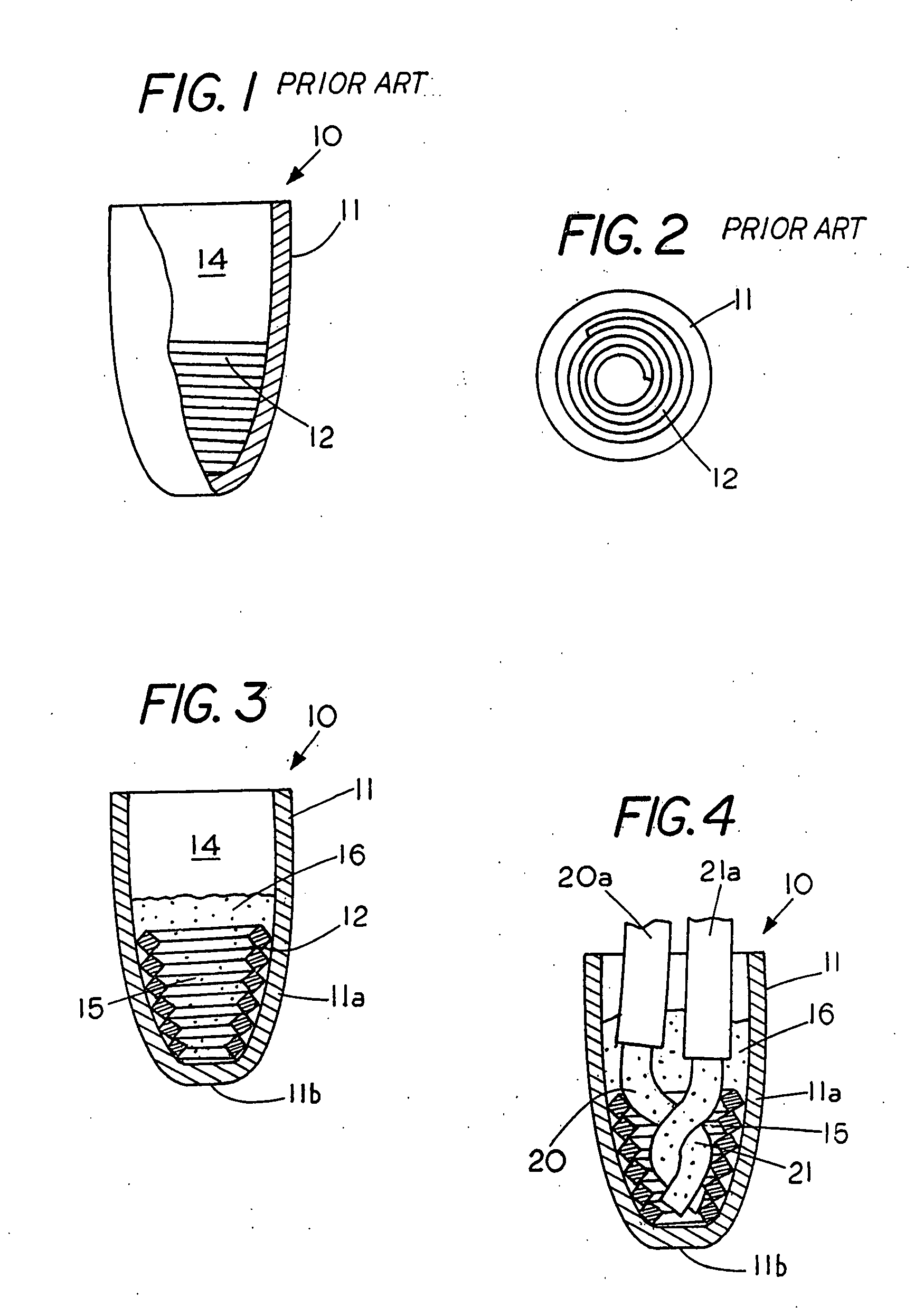
[0039]FIG. 1 is a partial sectional view of a prior art twist-on wire connector 10 usable with the present invention. Twist-on wire connector 10 has an electrically insulated housing 11 and a spiral thread 12 secured to the insulated housing 11. The spiral thread engages the ends of wires and allows the wires to brought into electrical contact with each other by rotating the twist-on wire connector 10 with respect to the ends of the wires.

[0040]FIG. 2 is a top view of a prior art twist-on connector 10 of FIG. 1 showing the spiral thread 12 for engaging the wires located centrally within the electrically insulated housing 11.

[0041]FIG. 3 is a section view of the prior art twist-on wire connector of FIG. 1 with a mass of a cohering gel 16 located therein. Twist-on wire connector 10 comprises an encircling sidewall 11a and an end wall 11b that mates with side wall 11a to form a chamber 14 within the electrically insulated housing 11. The spiral thread 12 is shown in cross section to ...


PUM

PropertyMeasurementUnit
pressureaaaaaaaaaa
pressureaaaaaaaaaa
pressureaaaaaaaaaa

Abstract

A twist-on wire connector containing a mass of a cohering gel in a gel state therein for forming a protective covering over a wire connection in the twist-on wire connector with the gel thereon removal from the twist-on wire connector and peelable from the wire connection to enable one to quickly form a further wire connection without having to wipe off the wire connection.

Description

CROSS REFERENCE TO RELATED APPLICATIONS [0001] This application claims priority from provisional patent application 60 / 653,215 filed Feb. 15, 2005 titled Twist-on Wire Connector.STATEMENT REGARDING FEDERALLY SPONSORED RESEARCH OR DEVELOPMENT [0002] None REFERENCE TO A MICROFICHE APPENDIX [0003] None FIELD OF THE INVENTION [0004] This invention relates generally to twist-on wire connectors and, more specifically, to twist-on wire connectors carrying a gel in a gel state therein for forming a protective covering around a wire connection yet allowing the user to quickly strip the protective covering from the wire if the wire connection needs to reformed. BACKGROUND OF THE INVENTION [0005] Wire connectors that connect two or more electrical wires together are widely known and used because of convenience and the ability to quickly form a low resistance electrical connection between two or more wires. Generally, there are two categories of wire connectors, twist-on wire connectors and non...

Claims


Application Information

Patent Timeline
Patent Type & Authority Applications(United States)
IPC IPC(8): H01R4/22H01R43/00
CPCH01R4/22H01R4/70H01R13/5216Y10T29/49204Y10T29/4922Y10T29/49211Y10T29/49201Y10T29/49224
Inventor KING, LLOYD HERBERT JR.BELGERI, MICHAELKEEVEN, JAMESHINER, WILLIAM
Owner THE PATENT STORE
Why Eureka
Try Eureka