Display Device, Viewing Angle Control Device, And Electronic Device

a control device and display device technology, applied in the direction of electric digital data processing, instruments, computing, etc., can solve the problems of increasing the total thickness and weight of the device, reducing the light transmission from the display device, and deteriorating display quality

Active Publication Date: 2008-03-06
SHARP KK
View PDF43 Cites 122 Cited by
  • Summary
  • Abstract
  • Description
  • Claims
  • Application Information

AI Technical Summary

Benefits of technology

[0012] The present invention was done to solve the problems above, and the objective of the present invention is to provide a built-in touch sensor d

Problems solved by technology

This, however, has induced such a problem that a person around the user can peek a confidential document and personal information.
In case where a touch sensor is combined with one of various types of electronic devices by pasting a touch panel onto the front surface of the electronic device, the transmittance of light from the display device is reduced because the touch panel is provided on the display screen of the electronic device, i.e. pro

Method used


Image

  • Display Device, Viewing Angle Control Device, And Electronic Device
  • Display Device, Viewing Angle Control Device, And Electronic Device
  • Display Device, Viewing Angle Control Device, And Electronic Device

Examples


embodiment 1

[0095] The following will describe an embodiment of the present invention with reference to FIGS. 1-19.

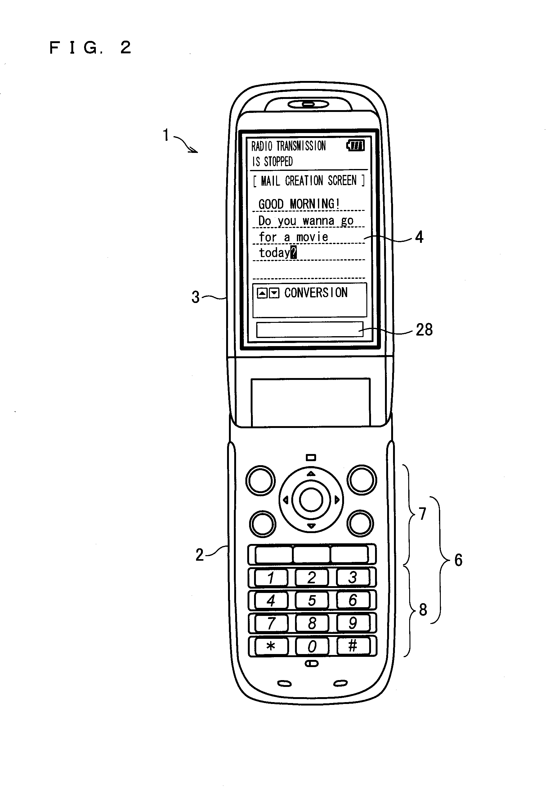
[0096]FIG. 2 shows the exterior appearance of a mobile phone (electronic device) 1 of an embodiment of the present invention. The mobile phone 1 of the present embodiment, which is a so-called clamshell type, is opened in the figure. Since the illustrated surface is hidden inside when the mobile phone 1 is closed and is on the side that the user mainly use when the mobile phone 1 is opened, this surface shown in FIG. 2 is termed a front surface in the present embodiment.

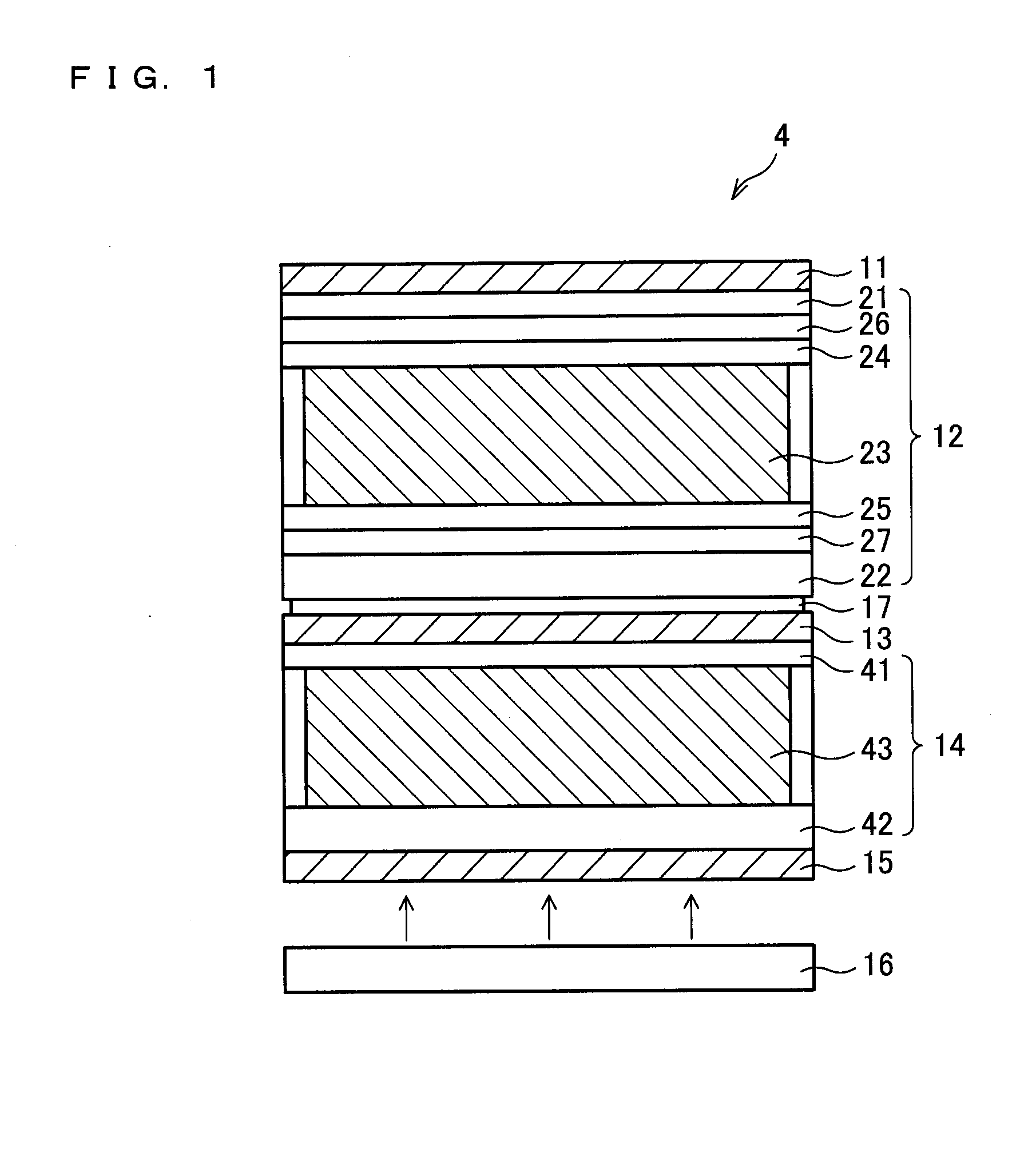
[0097] As shown in FIG. 2, the mobile phone 1 is constituted by a main body 2 and a cover 3. The main body 2 is hinged with the cover 3. On the front surface of the cover 3, a display section (display device) 4 is provided.

[0098] The front surface of the main body 2 is provided with main operation buttons 6. The main operation buttons 6 are constituted by: function buttons 7 for various settings and function swit...

example 1

of Liquid Crystal Molecule Alignment of SW-LCD

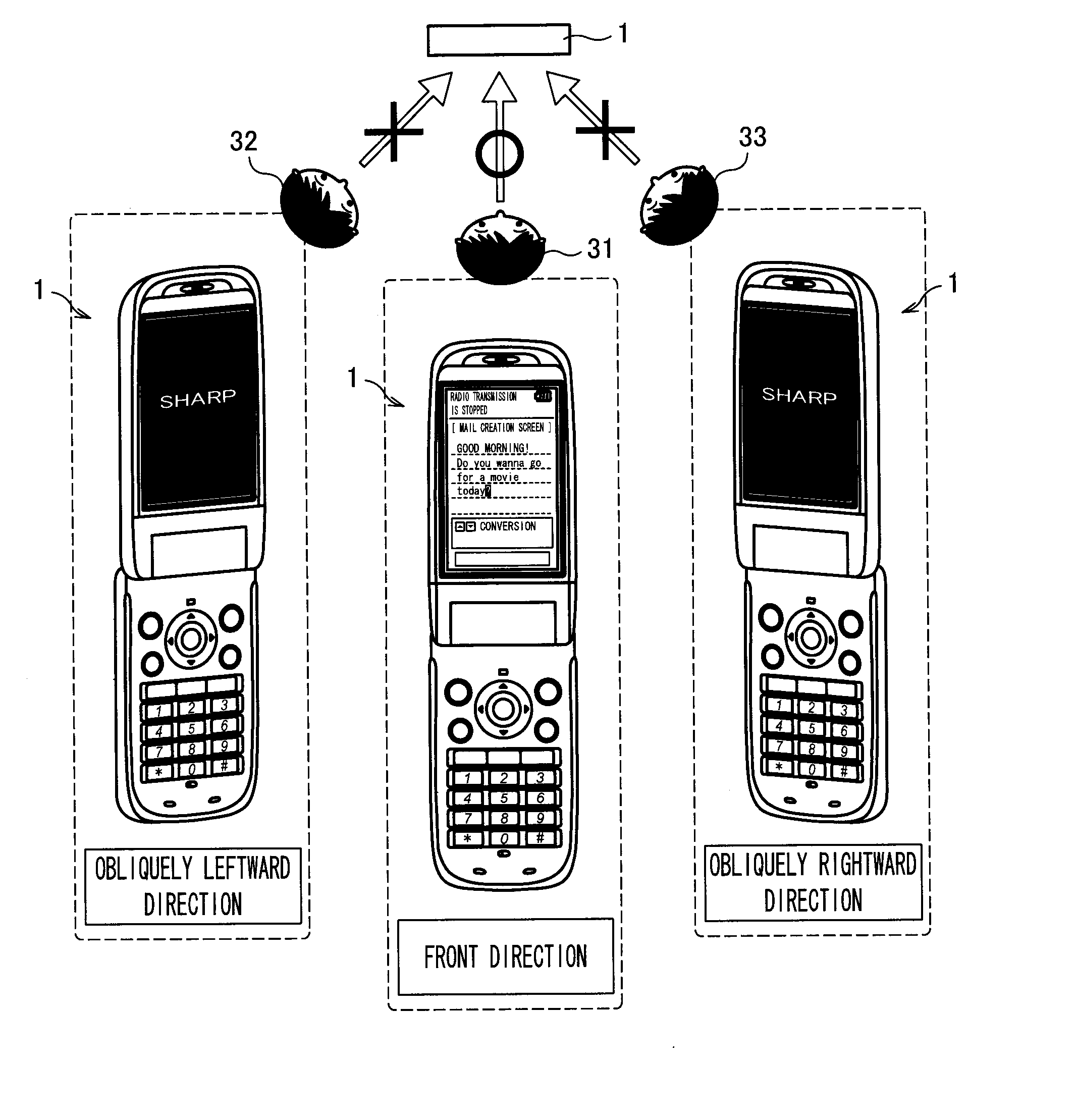
[0111]FIG. 5(a) shows a display screen on the display section 4 of the mobile phone 1. In the figure, the vertical direction in the figure corresponds to the vertical direction of an image on the main LCD 14. Hereinafter, the horizontal direction on the display image (i.e. horizontal direction on the figure) is termed x direction, the vertical direction on the display image (i.e. vertical direction on the figure) is termed y direction, and the direction along the thickness of the display section 4 is termed z direction. In FIGS. 5(a)-10(b), the first transparent electrode film 26, the second transparent electrode film 27, and the alignment films 24 and 25 are omitted for the sake of simplicity.

[0112] According to FIG. 5(a), first, the polarization transmission axes of the second polarizing plate 11 and the first polarizing plate 13 are provided along the y direction. The rubbing directions of the alignment films 24 and 25 are made so as...

example 2

of Liquid Crystal Molecule Alignment of SW-LCD

[0125] An example 2 of the liquid crystal molecule alignment of the SW-LCD will be discussed with reference to FIG. 8. Used in the example 2 of the liquid crystal molecule alignment of the SW-LCD shown in FIG. 8 is an SW-LCD 12′ which adopts alignment films made of a vertically-aligned polyimide material, instead of the alignment films 24 and 25 used in the above-described example 1 of the liquid crystal molecule alignment of the SW-LCD. With this, as shown in FIG. 8(a), liquid crystal molecules are aligned to be orthogonal to the surfaces of the substrates 21 and 22.

[0126] In this case, when no voltage is applied, the liquid crystal molecules of the SW-LCD 12′ are in uniaxial alignment so as to be orthogonal to the substrates 21 and 22. In FIG. 8(b), therefore, the liquid crystal molecule 37a looks like a perfect circle from right in front (i.e. for the viewer 31). When viewed in directions other than the front direction, the longitudi...


PUM


Abstract

A first transparent electrode film, which is a component of a SW-LCD for viewing angle control, is used as a touch panel. When a contacting object contacts the surface of the first transparent electrode film, a position detector detects currents flowing from plural parts of the first transparent electrode film so as to detect the contacting position of the contacting object, with reference to the detection result. With this, it is possible to provide a built-in touch sensor display device which is thin, lightweight, and low-cost, a viewing angle control device, and an electronic device.

Description

BACKGROUND OF THE INVENTION [0001] 1. Field of the Invention [0002] The present invention relates to a display device, a viewing angle control device, and an electronic device, and more specifically to a display device which can switch to a mode in which an image to be viewed changes depends on the viewing direction and which can detect which position on a display screen is touched by a pen or a finger, a viewing angle control device, and an electronic device. [0003] 2. Description of the Related Art [0004] The weight of electronic devices has recently been reduced, with the result that electronic devices with displays, such as mobile phones and mobile PCs, can now be used in public spaces. This, however, has induced such a problem that a person around the user can peek a confidential document and personal information. [0005] To solve this problem, there is proposed a display device which is usually set in a wide viewing angle display mode and can be set in a narrow viewing angle di...

Claims


Application Information

Patent Timeline
IPC IPC(8): G09G3/36
CPCG02F1/13338G06F3/0412G09G2320/068G09G2320/028G09G3/3611G06F3/0444
Inventor YABUTA, KOJIFUKUSHIMA, HIROSHITAKATANI, TOMOOIMAI, AKIRA
Owner SHARP KK
Why Eureka
Try Eureka