Tire designing method, computer-readable recording medium, and tire manufacturing method

a technology of computer-readable recording medium and tire, which is applied in the field of tires, can solve the problems of vehicle vibration, uneven wheel and rim, and difficulty in manufacturing tires having perfectly uniform circumference tire uniformity, and achieve the effect of reducing vehicle vibration, reducing vehicle vibration, and improving tire uniformity

Inactive Publication Date: 2008-03-06
NAKAMURA SACHIO +1
View PDF7 Cites 4 Cited by
  • Summary
  • Abstract
  • Description
  • Claims
  • Application Information

AI Technical Summary

Problems solved by technology

Because of the structural and manufacturing constrains, it is difficult to manufacture a tire having perfectly tire uniformity along the circumference.
The non-uniformity of the tire properties may result in vehicle vibration such as “shakes” or “flutter”, and vehicle interior noises such as “booming noise” or “beat noise”.
Because the technology disclosed in Japanese Patent Application Laid-open No. 2005-534540 is used to evaluate a tire that is mounted on the rim of a wheel, the unevenness of the wheel and the rim affects the evaluation.
Hence, the evaluation results are not for the tire only but for the tire-wheel assembly, which makes it difficult to evaluate and improve the uniformity of the tire.

Method used


Image

  • Tire designing method, computer-readable recording medium, and tire manufacturing method
  • Tire designing method, computer-readable recording medium, and tire manufacturing method
  • Tire designing method, computer-readable recording medium, and tire manufacturing method

Examples


Embodiment Construction

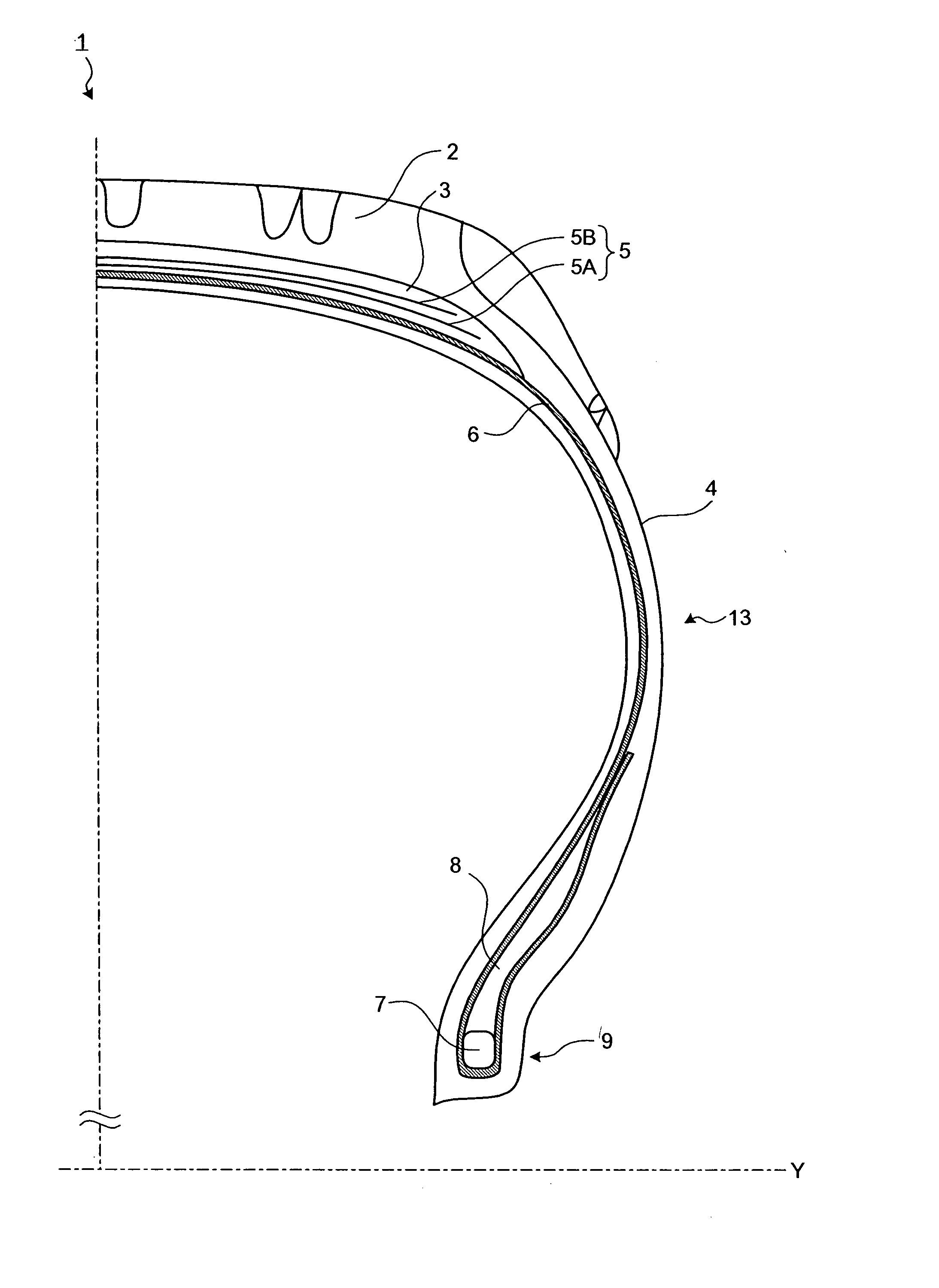
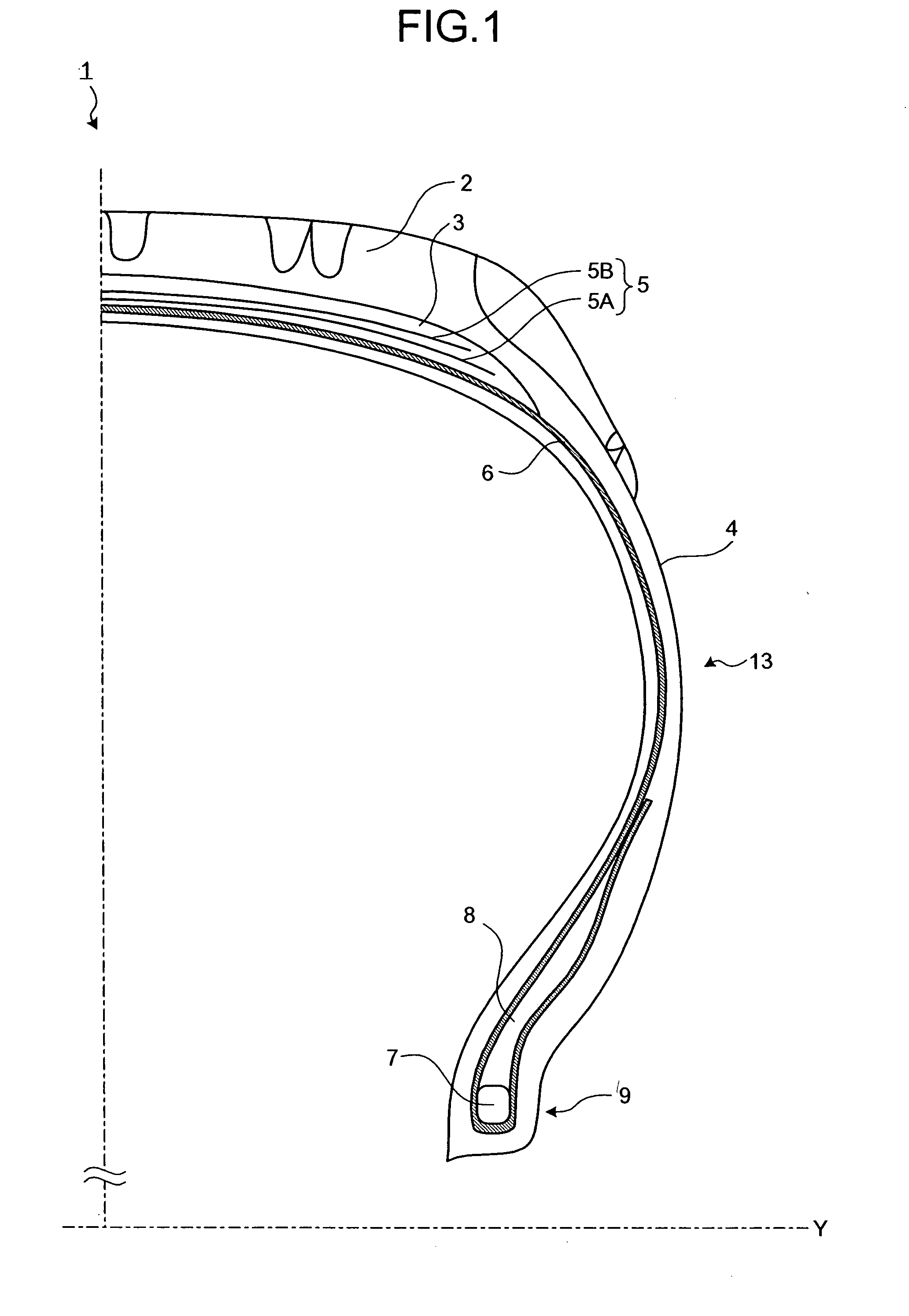
[0023] Exemplary embodiments of the present invention are explained in detail below with reference to the accompanying drawings. The present invention is not limited to the embodiments.

[0024]FIG. 1 is a partial meridian cross section of a typical pneumatic tire 1. The dashed-and-dotted line Y represents the rotation axis of the tire 1. The tire 1 is a complex structure including structural elements such as rubber, steel cords, and fibers as explained below. A cap tread 2 is a rubber layer that is in contact with the road surface and covers the outer surface of a carcass 6, a first belt 5A and a second belt 5B (collectively referred to as a “belt 5”). An under tread 3 is a rubber layer positioned between the cap tread 2 and the belt 5. A side tread 4 is positioned at the outermost portion of a sidewall 13. The presence of the side tread 4 protects the carcass 6 from damage due to external forces. The belt 5 is a cord layer laminated with rubber positioned between the cap tread 2 and...


PUM

PropertyMeasurementUnit
center angleaaaaaaaaaa
speedaaaaaaaaaa

Abstract

Evaluation tires, each having a plurality of structural elements including a target structural element, are prepared. Only the experimental structure of the target structural element is different among all the evaluation tires, while the structures of other structural elements are identical. Radial force variation of each of the evaluation tires is measured. Corrected radial-force variation of each of the evaluation tires is calculated by subtracting a 1st order component of the radial force variation from the radial force variation, and the structure of the target structural element is determined based on the corrected radial-force variations of the evaluation tires. This process is repeated for other structural elements.

Description

CROSS-REFERENCE TO RELATED APPLICATIONS [0001] This application claims the benefit and priority to Japanese Application Number 2006-225230 filed on Aug. 22, 2006, the disclosure of which is hereby incorporated by reference in its entirety. BACKGROUND OF THE INVENTION [0002] 1. Field of the Invention [0003] The present invention generally relates to tires, and specifically relates to methods of designing and manufacturing tires. [0004] 2. Description of the Related Art [0005] When a tire rotates under a load, it is desirable that the reaction variation caused with respect to the rotation axis of the tire is constant along the circumference of the tire. To realize such constant variation, it is necessary that inner rigidity, size, mass distribution, and the like (hereinafter, tire properties) are even in the tire along the tire circumferential direction. The evenness of the tire properties is collectively referred to as “tire uniformity”. A tire has a complex structure including rubbe...

Claims


Application Information

Patent Timeline
Patent Type & Authority Applications(United States)
IPC IPC(8): G06F19/00B29D30/00B60C19/00G01M1/16G01M17/02
CPCB60C99/006B29D30/0061
Inventor NAKAMURA, SACHIODAISHO, YASUJIRO
Owner NAKAMURA SACHIO
Why Eureka
Try Eureka