Multi-height ramp injector scramjet combustor

a combustor and ramp technology, applied in continuous jet plants, machines/engines, mechanical equipment, etc., can solve the problems of difficult fuel distribution, difficult fuel penetration and air-fuel mixing, and difficult fuel distribution to the inner regions of the combustion chamber

Inactive Publication Date: 2008-03-13
ROCKETDYNE
View PDF18 Cites 19 Cited by
  • Summary
  • Abstract
  • Description
  • Claims
  • Application Information

AI Technical Summary

Benefits of technology

[0004]The present invention is directed toward a multi-height ramp injection and flameholding system for use in a supersonic propulsion system. The injection system comprises a plurality of multi-height ramp injectors for introducing a fuel into an airflow in a combustor. In one embodiment of the invention, the multi-height ramp injectors comprise a plurality of tall injectors for fueling an inner portion of the airflow, and a plurality of short injectors for fueling an outer portion of the airflow. Multiple height ramp injectors are included to optimize the fuel distribution pattern and mixing.

Problems solved by technology

Obtaining an ideal, uniform fuel distribution is very difficult.
A challenge to using axi-symmetric scramjet combustors is the difficulty in achieving efficient fuel penetration and air-fuel mixing, particularly in circular cross-sections.
However, distributing fuel to the inner regions of the combustion chamber is difficult with wall injectors since the fuel must be injected at very high pressures such that it is able to penetrate the airflow.
These pumps are typically large and heavy, which adds to the overall weight and complexity of the propulsion system.
For example, sufficiently increasing the pressure of the fuel to reach the center of the airflow can result in a combination of over-fueling the inner regions or poor lateral fuel distribution.
Thus, wall injectors provide significant design challenges in ramjet / scramjet propulsion systems.
Thus, pop-in strut injectors increase the size, weight, and overall complexity of the injector system, as well as creating thermal problems and sealing issues.

Method used


Image

  • Multi-height ramp injector scramjet combustor
  • Multi-height ramp injector scramjet combustor
  • Multi-height ramp injector scramjet combustor

Examples


Embodiment Construction

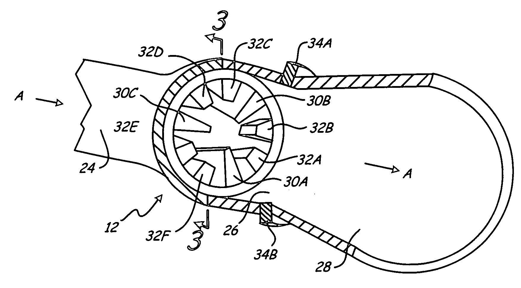
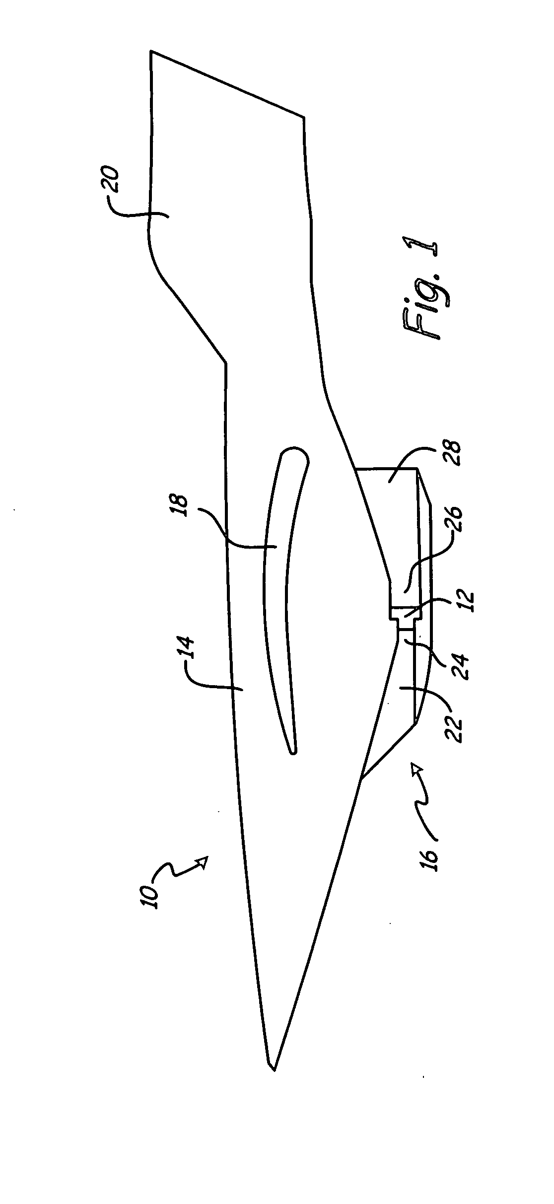
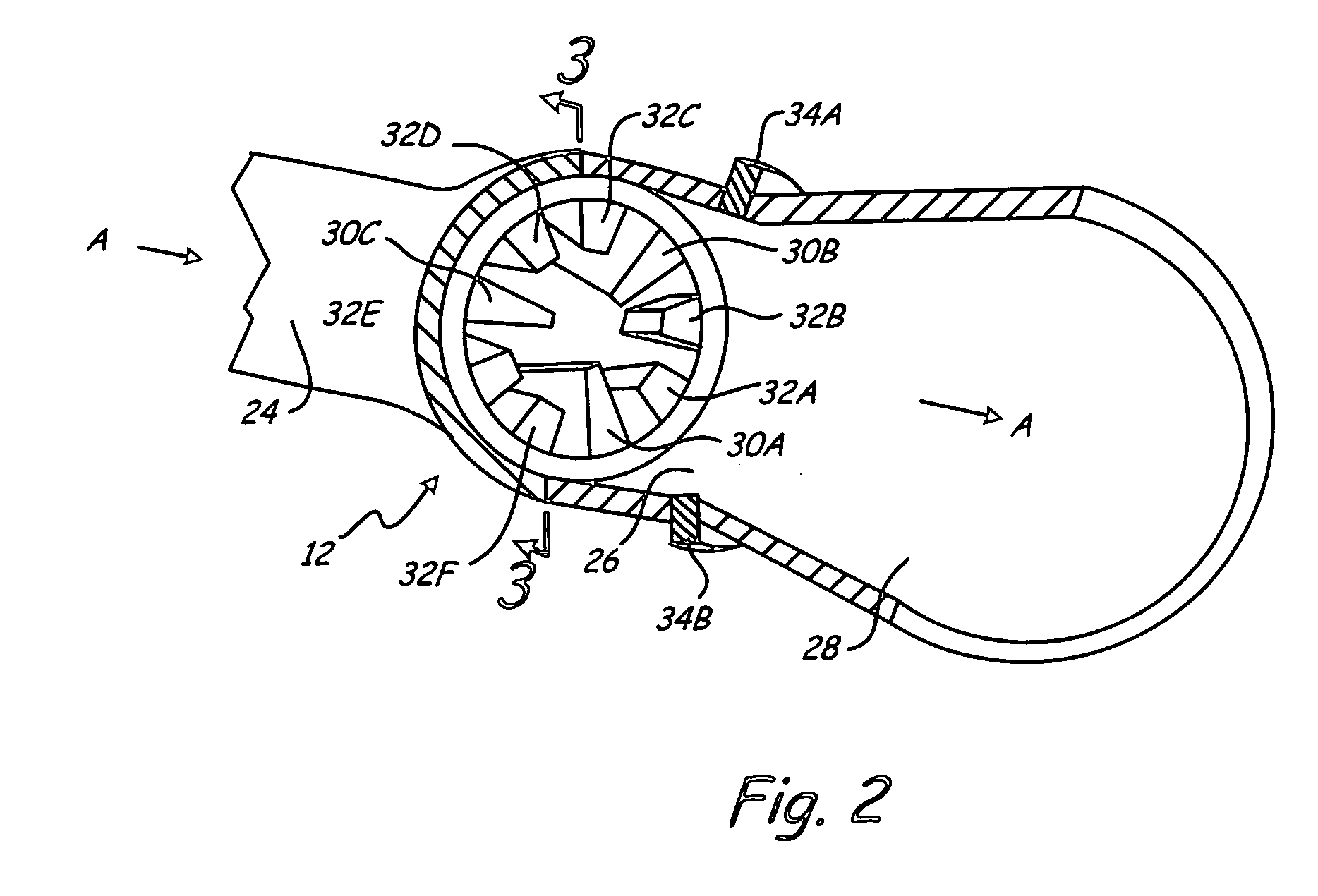
[0010]FIG. 1 shows ramjet / scramjet powered vehicle 10 in which injection system 12 of the present invention is used. Vehicle 10 includes fuselage 14, in which ramjet / scramjet propulsion system 16 is incorporated. Fuselage 14 includes structural components, such as wing 18 and tail fin 20, that lift vehicle 10 to flight when propelled at sufficient speeds by propulsion system 16. Vehicle 10 also includes other components required for controlling and propelling vehicle 10, such as flight control systems and fuel systems, which are not shown, but are well known in the aerospace industry. Propulsion system 16 includes inlet duct or nozzle 22, isolator 24, injection system 12, combustor 26 and exit nozzle 28. Propulsion system 16 acts to propel vehicle 10 at supersonic to hypersonic speeds utilizing ramjet and scramjet propulsion. In the embodiment'shown, vehicle 10 comprises a reusable aircraft such as for transporting people and equipment. However, in other embodiments, vehicle 10 comp...


PUM


Abstract

A multi-height ramp injection system, for use in a supersonic propulsion system, comprises a plurality of multi-height ramp injectors for variably introducing a fuel into an airflow in a combustor. In one embodiment of the invention, the multi-height ramp injectors comprise a plurality of tall injectors for fueling an inner portion of the airflow, and a plurality of short injectors for fueling an outer portion of the airflow.

Description

BACKGROUND OF THE INVENTION[0001]This invention relates generally to supersonic engines and more particularly to fuel injection systems for ramjet / scramjet propulsion systems. Air breathing ramjet engines typically propel vehicles to supersonic speeds above Mach 3, and air breathing scramjet engines typically propel vehicles to hypersonic speeds greater than about Mach 7. Air breathing ramjet / scramjet engines produce thrust by supersonically accelerating compressed air through a flow path. Cylindrical axi-symmetric scramjet engines are particularly useful for missile applications due to their circular or elliptical cross-sections, which decreases combustor weight and have sound structural integrity. The compressed air is directed into a combustion chamber where a fuel injection system delivers fuel to the compressed air whereby a combustible air-fuel mixture is produced. The air-fuel mixture is burned and then expanded through a nozzle to create thrust. To facilitate mixing and to o...

Claims


Application Information

Patent Timeline
Patent Type & Authority Applications(United States)
IPC IPC(8): F02K7/10
CPCY02T50/671F02K7/10Y02T50/60
Inventor MORRISON, CALVIN Q.EDELMAN, RAYMOND B.
Owner ROCKETDYNE
Why Eureka
Try Eureka