Splice plate for stringers and orbital joining device

a technology of orbital joining device and splice plate, which is applied in the direction of rail fasteners, transportation and packaging, and ways, etc., can solve the problems of difficult design and size of stringers, difficult to machine prior art splice plates, and high fatigue resistance of splice plates

Inactive Publication Date: 2008-03-20
AIRBUS OPERATIONS (SAS)
View PDF26 Cites 47 Cited by
  • Summary
  • Abstract
  • Description
  • Claims
  • Application Information

AI Technical Summary

Problems solved by technology

In particular, because of their single-piece structure and complex geometry, the prior art stringer splice plates are difficult to machine.
These variations in the orientation of the fibers of the stringer splice plates generates major secondary bending moments which make it difficult to design and size these stringers and make said splice plates very sensitive to fatigue.
Inasmuch as the stringer splice plates in particular have a function of transferring the longitudinal stresses induced by the bending of the panels to which they a

Method used


Image

  • Splice plate for stringers and orbital joining device
  • Splice plate for stringers and orbital joining device
  • Splice plate for stringers and orbital joining device

Examples


Embodiment Construction

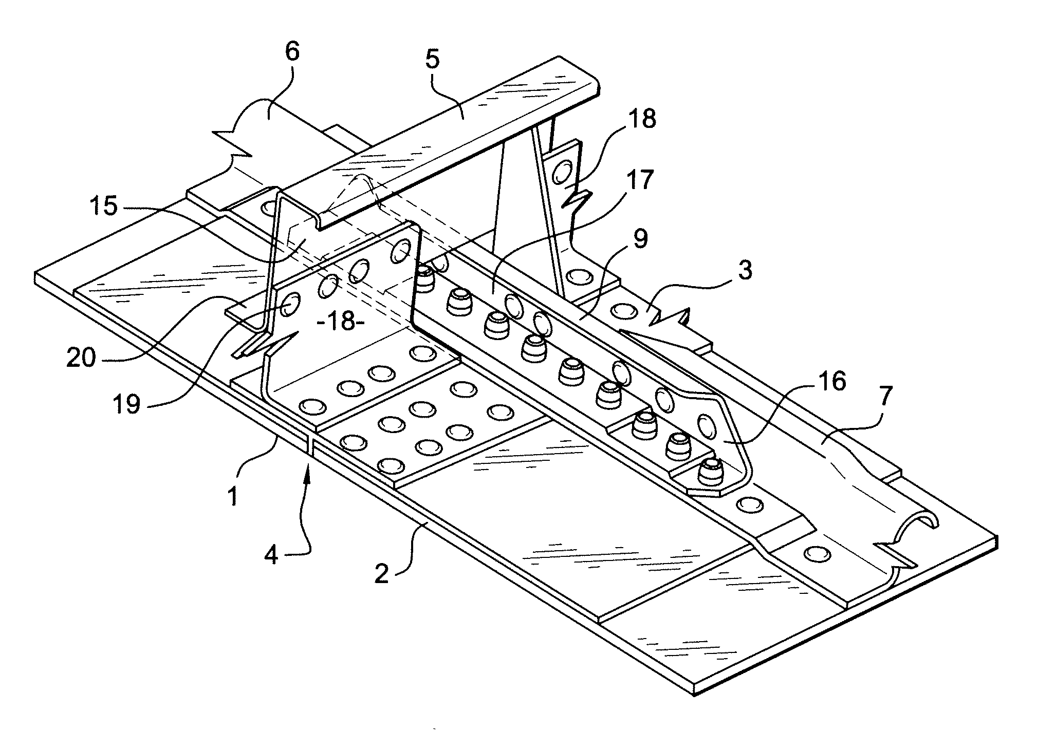
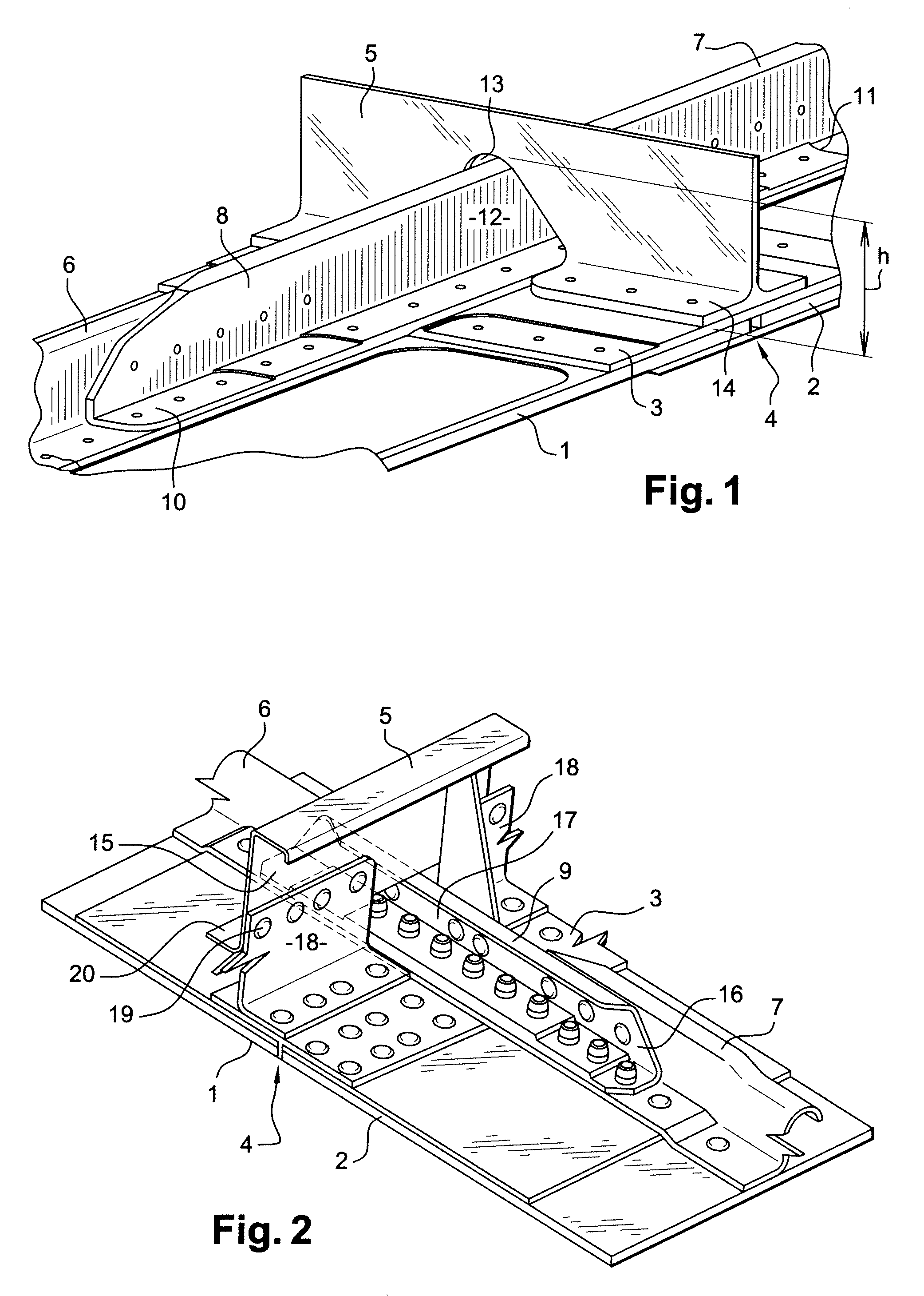
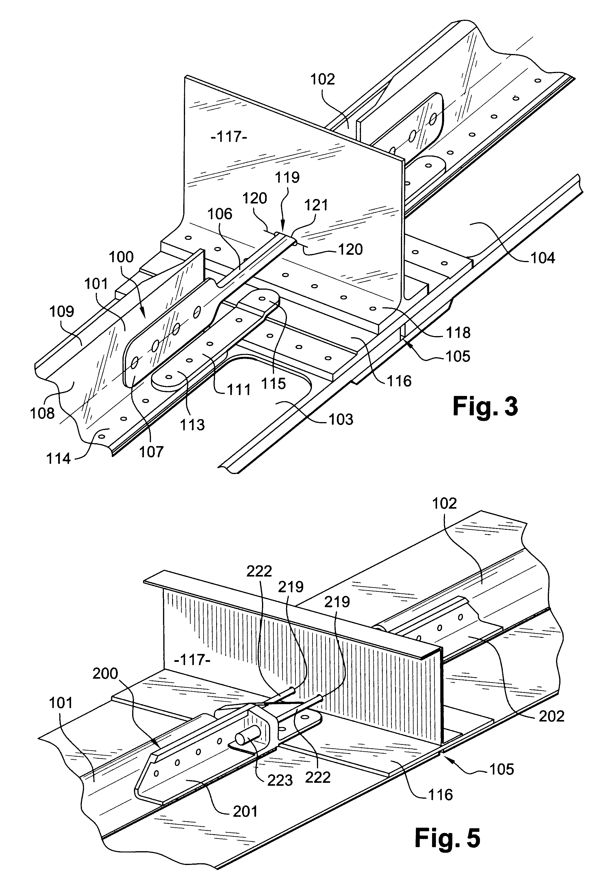
[0048]FIGS. 3 and 4 show a stringer splice plate 100 according to the disclosed embodiments.

[0049]The stringer splice plate 100 is used here to fixedly join two stringers 101 and 102 positioned one in the extension of the other and facing each other, each of the stringers 101,102 being fixedly joined to a panel 103,104. The two panels extend one in the extension of the other and are attached by one entire side in a zone of attachment 105.

[0050]The stringer splice plate 100 has a connection rod 106 spanning the space made between the two stringers 101,102. A first extremity 107 of the connection rod 106 is fixedly joined to a flank 108 of the web 109 of the first stringer 101, while the second extremity 110 of the connection rod 108 is fixedly joined to a flank 108 of the web 109 of the second stringer 102. The two extremities 107,110 of the connection rod 106 form flat ties having one element that extends in parallel to the longitudinal axis of the connection rod 6, so as to be atta...


PUM


Abstract

A splice plate for stringers designed to connect two adjacent stringers at least three independent pieces, a connection rod being designed to be fixed by two opposite extremities to two adjacent stringers, and at least two connecting plates, each connecting plate being designed to be fixedly joined to a first extremity of one of the two stringers, and by a second extremity of a cross bar disposed between the two stringers. The disclosed embodiment also relate to a device for orbital fixation including at least one stringer splice plate splice bar.

Description

BACKGROUND[0001]1. Field[0002]The disclosed embodiments relate to a splice plate for stringers or “stringer splice plate” designed to connect two adjacent stringers. The term “stringer splice plate” is understood to mean a part designed to provide the linkage and alignment of two stringers that are adjacent (i.e. side by side or one in the extension of the other) and the transmission of certain stresses between these two stringers, said stringers being positioned along the longitudinal profile of a structure for which they provide the stiffening. The disclosed embodiments also relate to an orbital joining device designed to fixedly join two adjacent panels of an aircraft fuselage, said orbital joining device comprising at least one stringer splice.[0003]The stringer splice plate according to the disclosed embodiments can be used in all fields where it is required to physically link two adjacent parts so as to maintain the link, alignment and transmission of certain stresses between ...

Claims


Application Information

Patent Timeline
IPC IPC(8): B64C1/06E01B9/02
CPCB64C1/064B64C2001/0081B64C1/069
Inventor MEYER, CEDRIC
Owner AIRBUS OPERATIONS (SAS)
Why Eureka
Try Eureka