Liquid crystal television

a technology televisions, which is applied in the field of liquid crystal televisions, can solve the problems of high cost, inability to select the wiring path of lead wires, and high cost by about 0.2 us dollars per tube, and achieve the effect of keeping cost low and cost low

Inactive Publication Date: 2008-03-20
FUNAI ELECTRIC CO LTD
View PDF2 Cites 5 Cited by
  • Summary
  • Abstract
  • Description
  • Claims
  • Application Information

AI Technical Summary

Benefits of technology

[0017]According to such configuration, the audio signal is transmitted to the sensor substrate by the cable conventionally covered with protective cable, and the audio signal is transmitted from the sensor substrate to the right speaker and the left speaker through lead wires that pass through a passage that does not need to be covered with a protective cable. The cable may be bundled beforehand, or plural cables may be bundled. The protective tube is a flame retardant tube provided to electrically insulate the outside and the inside of the tube and to protect the interior of the tube from breaking.
[0018]In other words, since the cable for connecting the connector of the substrate and the sensor substrate is covered with a protective tube, the cable will not be broken by the left bridge frame or the right bridge frame. The lead wires connected from the sensor substrate to the speakers will not interfere with the left bridge frame or the right bridge frame since the right bridge frame and the right bridge frame are positioned on the rear face side compared to the liquid crystal panel, and the sensor substrate is positioned on the front surface side compared to the liquid crystal panel. This can eliminate the need of covering the lead wires with a protective tube. In other words, with use of the cable that is normally required for transmitting signals and that needs to be covered with a protective tube, signals are transmitted to the sensor substrate. This can eliminate the need of more new protective tubes and keep cost low.
[0019]According to the aspect of the present invention, the audio signal is transmitted to the sensor substrate by the cable covered with a protective cable, and the audio signal is transmitted from the sensor substrate to the right speaker and the left speaker through lead wires passing through the passage that do not need to be covered with protective cable, making it possible to provide a liquid crystal television with its cost kept low.

Problems solved by technology

Liquid crystal televisions however have lesser spaces for arranging lead wires as compared to cathode ray televisions and plasma televisions, leading to necessary consideration to creeping distance from a power supply circuit (in particular, primary side) and interference with the edges of other components and thus causing the difficulty in selecting the wiring path of the lead wire.
The UL tube is a tube made of flame retardant rubber, which suffers from high cost by about 0.2 US dollars per tube.
Thus, the UL tube must be used for the lead wire, and high cost is inevitable.
Such problem cannot be solved with the techniques of the documents described above.

Method used

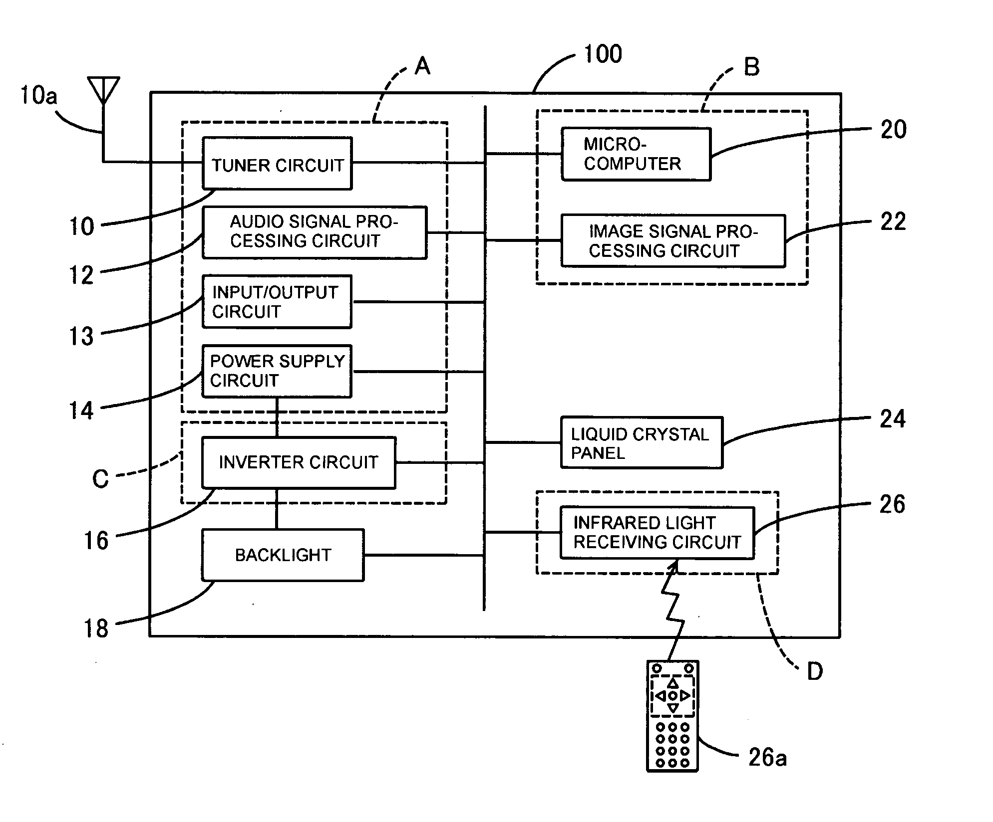
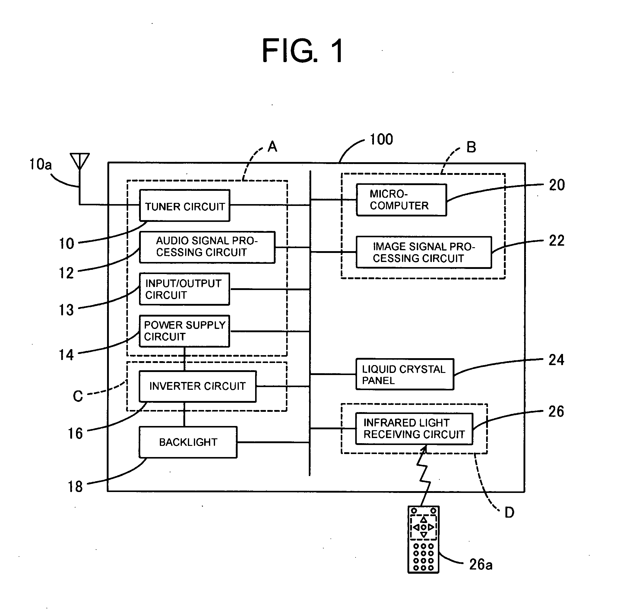
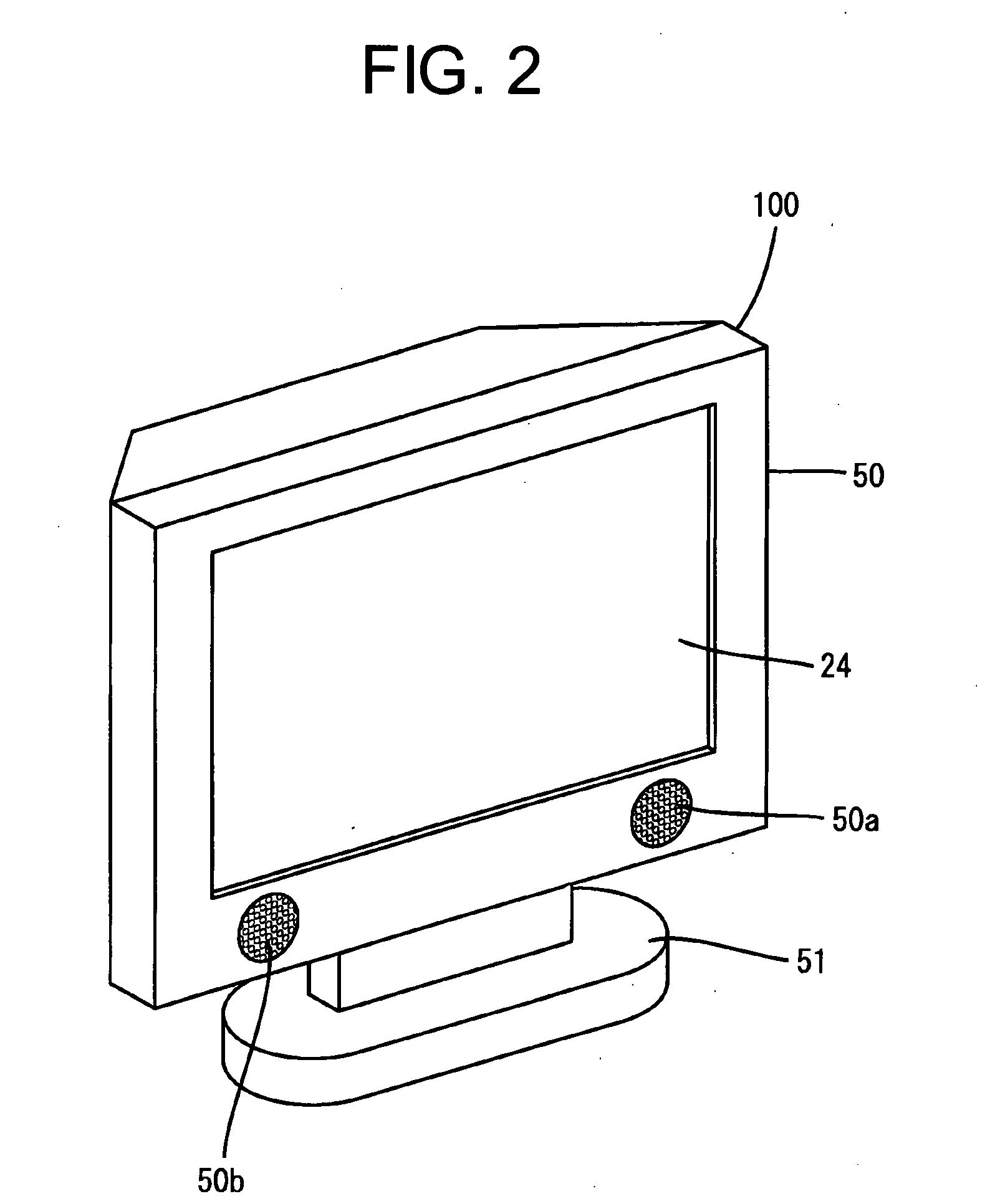

Image

  • Liquid crystal television
  • Liquid crystal television
  • Liquid crystal television

Examples


Embodiment Construction

[0028]The detailed description set forth below in connection with the appended drawings is intended as a description of presently preferred embodiments of the invention and is not intended to represent the only forms in which the present invention may be constructed and or utilized.

[0029]Although the invention has been described in considerable detail in language specific to structural features and or method acts, it is to be understood that the invention defined in the appended claims is not necessarily limited to the specific features or acts described. Rather, the specific features and acts are disclosed as preferred forms of implementing the claimed invention. Therefore, while exemplary illustrative embodiments of the invention have been described, numerous variations and alternative embodiments will occur to those skilled in the art. For example, such variations and alternate embodiments are contemplated, and can be made without departing from the spirit and scope of the invent...


PUM

PropertyMeasurementUnit
aspect ratioaaaaaaaaaa
flexibleaaaaaaaaaa
rectangular shapeaaaaaaaaaa

Abstract

An audio signal is transmitted to a sensor substrate D through a cable 60c connecting the lower end of an analog substrate A arranged on the rear face of the liquid crystal panel and the sensor substrate arranged below the liquid crystal panel of a cabinet. The cable 60c is covered with UL tube in advance, and connected by being passed through the inside of a horseshoe shape of a lower bridge pier portion 52b3 of the right bridge frame 52b. The audio signal is transmitted to the speakers 53a, 53b connected to the connectors 61a, 61b with lead wires by the pattern on the sensor substrate D.

Description

CROSS-REFERENCES TO RELATED APPLICATIONS[0001]The present application is related to the Japanese Patent Application No. 2006-252682, filed Sep. 19, 2006, the entire disclosure of which is expressly incorporated by reference herein.BACKGROUND OF THE INVENTION[0002](1) Field of the Invention[0003]The present invention relates to liquid crystal televisions, in particular, to a liquid crystal television in which a substrate mounted with an audio signal processing circuit is arranged on the rear face side of a liquid crystal panel.[0004](2) Description of Related Art[0005]In general, televisions have audio signal processing circuits that generate audio signals and output the audio signals to speakers attached to cabinets to thereby reproduce audios. Japanese Unexamined Patent Application Publication No. 9-327083 discloses a technique wherein a speaker is connected to a connector arranged on a substrate with a lead wire, through which the audio signal is transmitted to the speaker.[0006]J...

Claims


Application Information

Patent Timeline
Patent Type & Authority Applications(United States)
IPC IPC(8): G02F1/1333
CPCH04N5/64
Inventor TOMIKAWA, KAZUHIRO
Owner FUNAI ELECTRIC CO LTD
Why Eureka
Try Eureka